Solar equipment elevation diagrams: what plan reviewers check
A label-location key shows where placards belong. An equipment elevation is a scaled view looking straight at the wall. It shows the actual equipment, wall features, mounting heights and clearances.
For residential solar and battery permit designers. Updated October 15, 2026.
What an equipment elevation must show
A scaled view of the actual wall: equipment dimensions and mounting heights, every conduit run and its destination, doors, windows, vents and nearby gas equipment. Dimension the required working space, operating-handle heights and applicable battery separations. A generic arrangement on the labels sheet does not establish those distances.
Four things the reviewer needs to read
A correction received on a solar permit set put the missing information plainly:
“Elevations need to show all conduit runs and all details on the walls (windows, doors, etc.)”
That is a project-specific review comment, not a nationwide code quotation. It illustrates the four questions a useful elevation answers:
- Position
- Distance along the wall and height above finished grade (ground level) or floor.
- Size
- The selected equipment’s actual width and height, including relevant projections.
- Identity
- Equipment identifiers that match the one-line diagram and equipment schedule.
- Clearance
- Measured space for access, operation and the applicable installation requirements.
Draw the conduit through to its destination
Include the short connections between enclosures and the runs leaving the wall. When a run leaves this view, add a continuation note identifying its destination, such as “to roof junction box” or “through wall to existing indoor panel.” Show the remaining route on the appropriate plan or detail.
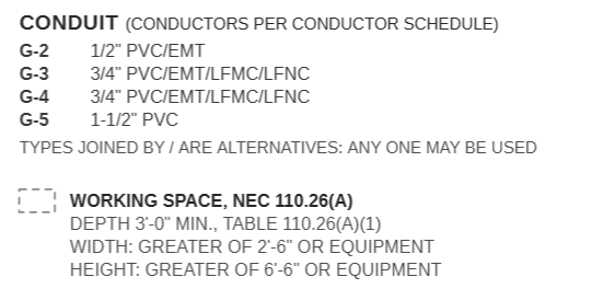
Keep the wall readable with short run tags such as G-2. Put conduit size and type in a nearby key, and use the same run identifier in the conductor schedule. The elevation explains the physical route; the schedule identifies the conductors inside it.
Include the openings, then apply the right battery rule
Draw doors, windows, vents, wall corners and nearby gas equipment before placing the new equipment. Record what each opening serves. Show relevant features around a corner on an adjoining view or plan. State that a wall has no openings only when the site information establishes that fact.
For an energy storage system (ESS), three feet is a common separation, but the covered openings, measurement and exceptions depend on the adopted rules. Keep manufacturer installation clearances and local fire requirements distinct.
Local examples, not a universal three-foot rule
These examples show why the opening type and permit location matter. They do not establish the required clearance for a project in another jurisdiction.
Los Angeles County, September 2024: EG-10 addresses doors, windows, operable openings, heating and air-conditioning inlets and penetrations into habitable or occupiable spaces or bathrooms. Its guidance covers adjacent walls and gas-meter regulators, with additional vent criteria in Appendix C. The submittal instructions call for dimensions to specified features within seven feet of an ESS. Read EG-10, pages 6 and 12 and Appendix C.
City of Los Angeles, May 2023: LAFD’s exterior-ESS memo calls for more than three feet from openings, but also specifies conditions for certain dryer or kitchen exhausts, underfloor vents and access panels within that distance. Those conditions are not a blanket exemption for all vents. Read the memo and checklist.
Washington example, April 2025: MyBuildingPermit’s tip sheet, based on the 2021 IRC with Washington amendments, specifies three feet from doors and windows for exterior installations. Read Tip Sheet 26.
Use the requirements adopted for the project’s permit date. Do not erase a garage door or classify a vent as exempt to make a drawing pass. Show the feature and document the applicable treatment.
Working space has width, height and depth
National Electrical Code (NEC) 110.26(A) addresses equipment likely to require examination, adjustment, servicing or maintenance while energized. Draw its working space where a person actually stands. The dashed rectangle on an elevation shows width and height; it cannot, by itself, demonstrate the depth extending out from the wall.
- Width: 30 inches or the equipment width, whichever is greater
- The space need not be centered. Keep the required opening for equipment doors or hinged panels, at least 90 degrees.
- Height: 6 feet 6 inches or the equipment height, whichever is greater
- Measure from grade, floor or platform. Do not confuse this clear-space height with the maximum operating-handle height.
- Depth: select from Table 110.26(A)(1)
- Measure from the enclosure face, or exposed live parts when unenclosed. At 0–150 volts to ground, the minimum is 3 feet. A typical 120/240-volt dwelling service is 120 volts to ground. Other voltages and conditions can require more; do not apply that assumption to every solar direct-current (DC) circuit.
Sources: NFPA Code Talk: Electrical Room Basics, 2023 NEC discussion; Mike Holt’s Article 110 working-space table; IAEI’s working-space explanation.
The six-inch projection allowance in 110.26(A)(3) concerns associated electrical equipment above or below the equipment being worked on, measured beyond its front face. It is not permission for any nearby object to occupy the working space. Show depth and obstructions in a plan view, section or dimensioned detail.
Dimension the operating handle, not just the enclosure
For ordinary accessible switches and circuit breakers, NEC 240.24(A) and 404.8(A) generally limit the center of the operating-handle grip in its highest position to 6 feet 7 inches above the floor or working platform. The sections contain exceptions; this is not a universal enclosure-height limit. Michigan Tech’s electrical inspection FAQ explains the grip measurement, and Connecticut’s code training illustrates 404.8(A).
Define B.O. as bottom of equipment and T.O. as top of equipment, with a stated grade or floor reference. Then add the handle dimension where needed. A box-top dimension cannot prove handle height unless the handle’s position within that box is known.
Reading the example elevation
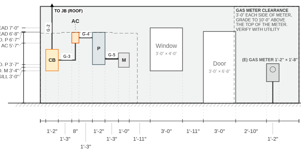
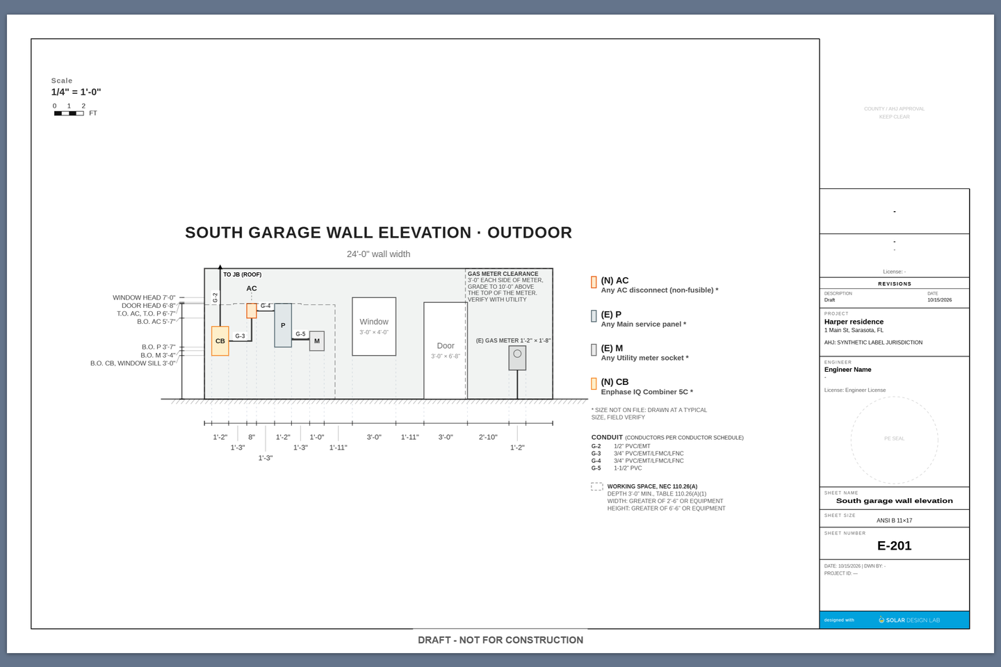
The full sheet names the south garage wall and its outdoor location. The equipment key distinguishes new from existing equipment. The window and door remain visible instead of disappearing behind equipment callouts.
This example demonstrates drawing organization, not a compliant battery installation: it contains no ESS, includes illustrative equipment sizes and is marked draft. Do not reuse its gas-clearance envelope as a general utility rule.
Choose a scale that keeps the exported drawing legible. Los Angeles County’s September 2024 guide specifies elevations at least 1/4 inch = 1 foot. At the final print size, check that the run tags, key and dimensions can be read without overlapping. EG-10, page 10.
Before submitting the sheet
- Match equipment identifiers and conduit tags to the one-line and schedules.
- Show the actual wall features and where each off-wall conduit run goes.
- Dimension mounting heights, operating handles and the applicable separations.
- Show working-space depth in a view that can actually measure it.
- Check the exported sheet at its intended print size.
For the rest of the permit package, see the solar planset requirements guide.
Common questions
- What if the site photos do not show the whole wall?
- Obtain a complete wall photo or measured site sketch before finalizing the elevation. Include nearby openings, corners and gas equipment. Do not use a typical arrangement to fill gaps in the site information.
- Does every solar project need an equipment elevation?
- The permitting authority sets the submittal requirements. An elevation is especially useful when wall openings, equipment heights or battery clearances cannot be understood from the site plan. Some authorities require one when those features cannot be clearly shown on another plan.
- Does the 30-inch working space have to be centered on the panel?
- No. The required width can extend more to one side, provided it includes the equipment, remains clear and permits equipment doors or hinged panels to open at least 90 degrees. Equipment wider than 30 inches needs at least its own width.
- Can I leave a garage door out of a battery elevation?
- Show it. Do not assume a garage door is exempt because it does not open directly into living space. Identify what the opening serves, dimension it and apply the permitting authority’s adopted requirements to that feature.
- Do vents count as openings near a battery?
- They can. Los Angeles city and county guidance both address vents, but their conditions differ. Identify the vent type, location and space it serves. A generic three-foot note cannot establish whether a particular vent arrangement is permitted.
- What scale should an equipment elevation use?
- Use the scale required by the permitting authority. Los Angeles County’s September 2024 guide gives one example: at least 1/4 inch equals 1 foot. Check the conduit tags and dimensions at the intended print size.
The local examples above describe dated agency documents. Confirm the current adopted edition and submittal requirements with the authority having jurisdiction (AHJ), meaning the office reviewing this permit.