Electrical
PV Interconnection Method Selector
Pick your service style and enter a few electrical inputs. See every interconnection method that fits, the real wiring diagram, the NEC code basis for your code cycle, and export a method sheet.
Inverter
Rated continuous AC output (max), not peak. Drives the 125% PV breaker per NEC 690.8.
Service style
Main panel
Explore more options by derating the main
A smaller main breaker frees up busbar headroom for the 120% rule, which can enable load-side backfeed interconnections.
1 method match your service
Backfeed Breaker
120% rule · NEC 705.12(B)(3)(2)
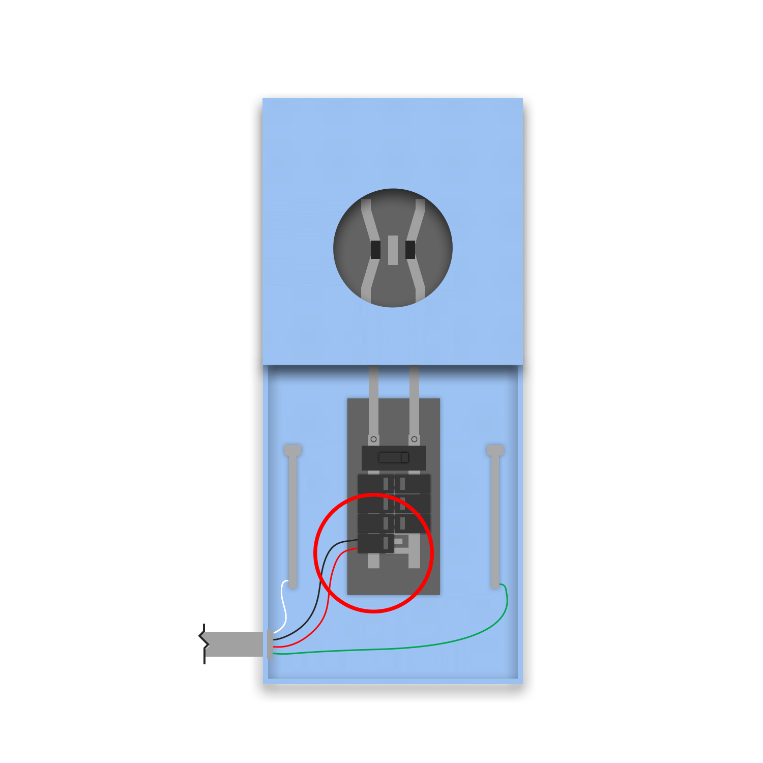
Backfeed breaker in a meter-main combo (no feedthrough panel) using the 120% rule.
Code basis
Backfeed-breaker connection on a meter-main combo busbar (no feedthrough panel). Governed by the 120% allowance against the combo bus: main OCPD + PV breaker ≤ 1.20 × busbar.
- 705.12(B)(2): 120% busbar allowance (Article 705 reorganized in 2023)
- 705.12(B)(2)(2)(c): opposite-end placement + label (renumbered)
- 690.8, 408.36, 250.122: unchanged in concept
Where should we send updates? The PDF downloads right away.
Render this interconnection as a real, auto-wired single-line.
About this calculator
The same interconnection logic our platform uses, free to use.
Choosing how a PV system connects to the service is one of the first decisions on every planset, and the one most likely to bounce in plan check when it is wrong. This tool runs the exact method-matching logic from the Solar Design Lab platform: it looks at your service style, busbar and main breaker ratings, and inverter output, then shows the interconnection methods that actually apply, from a load-side 120% backfeed to a supply-side tap to a feed-through tap.
Each method comes with the real wiring diagram and its NEC code basis. The 2020 and 2023 citations are both included because Article 705 was reorganized in 2023, so the section number a reviewer expects depends on the code cycle your jurisdiction has adopted. The PV backfeed breaker is sized automatically to 125% of your total continuous inverter output per NEC 690.8.
Educational reference, not project-specific engineering. Confirm the adopted code cycle, the AHJ's requirements, and the panel's listed busbar rating for every project.
Every interconnection method, with its NEC code basis
The complete reference, grouped by code concept. Each method shows the wiring diagram, a plain explanation, and the edition-aware citations (NEC 2020 and 2023). This library is generated from the same interconnection definitions our platform designs with, so it always matches the tool above.
120% Rule: Load-Side Backfeed
Solar lands on a backfed breaker on the busbar. Allowed when the main OCPD plus the PV breaker is no more than 120% of the busbar rating, with the PV breaker at the opposite end of the bus.
Load Side Connection (Default)NEC 705.12(B)(3)(2)
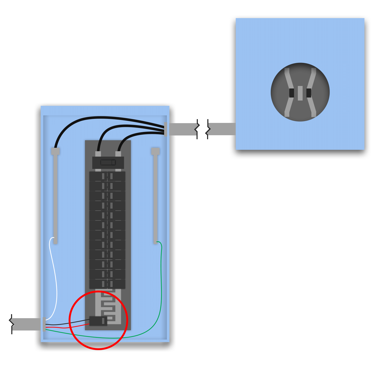
The default load-side interconnection: solar lands on a backfed breaker in the existing main service panel. The panel busbar is normally protected only by its main breaker (main ≤ bus). Adding solar as a second source from the opposite end of the bus is allowed because loads tap off BETWEEN the two sources, so no single bus segment ever carries both the full main and the full solar feed. NEC permits this when (main OCPD) + (PV breaker) ≤ 1.20 × busbar rating. The PV breaker is the next standard size at or above 125% of the inverter output current (690.8) and must sit at the OPPOSITE end of the bus from the main with a permanent "DO NOT RELOCATE" label, that placement is what makes the 20% headroom valid.
Default load-side backfeed-breaker connection on the main panel busbar, governed by the 120% allowance: main OCPD + PV breaker ≤ 1.20 × busbar rating.
- 705.12(B)(2): 120% busbar allowance (Article 705 reorganized in 2023)
- 705.12(B)(2)(2)(c): opposite-end placement + label (renumbered)
- 690.8, 408.36, 250.122: unchanged in concept
- 705.12(B)(3)(2): 120% busbar allowance (main OCPD + PV breaker ≤ 120% × busbar)
- 690.8(A)/(B): PV output is continuous; PV breaker ≥ 125% of inverter output current
- 408.36: backfed breaker on the panelboard busbar
- 705.12(B)(2)(3)(b): "DO NOT RELOCATE" label; PV breaker at the opposite end of the bus from the main
- 250.122: EGC sizing
- PV breaker MUST be at the opposite end of the bus from the main, with a permanent "DO NOT RELOCATE THIS OVERCURRENT DEVICE" label, that placement is what validates the 20% headroom.
- The 120% calc applies to the MAIN PANEL busbar: main OCPD + PV breaker ≤ 1.20 × busbar rating.
- MLO (no-main) panels cannot use this rule, there is no main to bound the calc; that is the supply-side case.
Backfeed Breaker - Main PanelNEC 705.12(B)(3)(2)
The canonical 120% case: on a Separate MDP service, solar lands on a backfed breaker in the existing main panel bus. No separate AC disconnect is added, the breaker itself is the OCPD. The bus is normally bounded by its main breaker; the PV breaker enters from the opposite end and loads tap off between the two sources, so no segment carries both at once. The connection is legal when (main OCPD) + (PV breaker) ≤ 1.20 × busbar rating, with the PV breaker sized at the next standard size ≥ 125% × inverter output (690.8) and placed at the opposite end of the bus from the main under a permanent "DO NOT RELOCATE" label.
Backfeed-breaker connection on the main panel busbar with the breaker as the OCPD. Governed by the 120% allowance: main OCPD + PV breaker ≤ 1.20 × busbar rating.
- 705.12(B)(2): 120% busbar allowance (Article 705 reorganized in 2023)
- 705.12(B)(2)(2)(c): opposite-end placement + label (renumbered)
- 690.8, 408.36, 250.122: unchanged in concept
- 705.12(B)(3)(2): 120% busbar allowance (main OCPD + PV breaker ≤ 120% × busbar)
- 690.8(A)/(B): PV output is continuous; PV breaker ≥ 125% of inverter output current
- 408.36: backfed breaker on the panelboard busbar
- 705.12(B)(2)(3)(b): "DO NOT RELOCATE" label; PV breaker at the opposite end of the bus from the main
- 250.122: EGC sizing
- PV breaker MUST sit at the opposite end of the bus from the main, under a permanent "DO NOT RELOCATE THIS OVERCURRENT DEVICE" label, that placement is what validates the 20% headroom.
- The 120% calc applies to the MAIN PANEL busbar: main OCPD + PV breaker ≤ 1.20 × busbar rating. If it fails, derate the main (Backfeed Breaker with Derate) or go supply-side.
- No separate disconnect, the backfed breaker is the OCPD. An MLO panel cannot use this rule (no main to bound the calc).
Backfeed Breaker with DerateNEC 705.12(B)(3)(2)
Same as Backfeed Breaker - Main Panel, but the existing main breaker is DERATED to a lower rating so the 120% sum clears. When (main OCPD) + (PV breaker) > 1.20 × busbar, swapping the main to a smaller standard size shrinks the first term until the inequality passes, the derated main still protects the busbar and the service conductors (240.4). The PV breaker still enters at the opposite end of the bus under a "DO NOT RELOCATE" label. The catch: the derated main must still be large enough to serve the dwelling's Article 220 calculated load, you cannot derate below what the loads actually draw.
Backfeed-breaker connection on the main panel busbar with the existing main breaker derated so (derated main + PV breaker) ≤ 1.20 × busbar. The derated main must still protect the conductors (240.4) and serve the calculated load (Art. 220).
- 705.12(B)(2): 120% busbar allowance (Article 705 reorganized in 2023)
- 705.12(B)(2)(2)(c): opposite-end placement + label (renumbered)
- 240.4, 690.8, 408.36, 250.122: unchanged in concept
- 705.12(B)(3)(2): 120% busbar allowance, satisfied by derating the main
- 240.4: the derated main breaker must still protect the busbar and service conductors
- 690.8(A)/(B): PV breaker ≥ 125% of inverter output current
- 408.36: backfed breaker on the panelboard busbar
- 705.12(B)(2)(3)(b): "DO NOT RELOCATE" label; PV breaker at the opposite end of the bus
- 250.122: EGC sizing
- PV breaker MUST sit at the opposite end of the bus from the main, under a permanent "DO NOT RELOCATE THIS OVERCURRENT DEVICE" label.
- The 120% calc applies to the MAIN PANEL busbar; the derate reduces the main OCPD term until (derated main + PV breaker) ≤ 1.20 × busbar.
- The derated main breaker must still PROTECT the conductors (240.4) AND still serve the Article 220 calculated load, do not derate below the actual demand.
Backfeed Breaker - Meter-MainNEC 705.12(B)(3)(2)
On a meter-main COMBO (meter + service main breaker + distribution bus in one enclosure) with no separate feedthrough panel, solar lands on a backfed breaker directly on the combo's distribution busbar. The combo's own main breaker bounds that bus; the PV breaker enters from the opposite end and loads tap off between the two sources. The 120% allowance applies to the COMBO busbar: (main OCPD) + (PV breaker) ≤ 1.20 × busbar rating, PV breaker sized at the next standard size ≥ 125% × inverter output (690.8), placed opposite the main under a "DO NOT RELOCATE" label.
Backfeed-breaker connection on a meter-main combo busbar (no feedthrough panel). Governed by the 120% allowance against the combo bus: main OCPD + PV breaker ≤ 1.20 × busbar.
- 705.12(B)(2): 120% busbar allowance (Article 705 reorganized in 2023)
- 705.12(B)(2)(2)(c): opposite-end placement + label (renumbered)
- 690.8, 408.36, 250.122: unchanged in concept
- 705.12(B)(3)(2): 120% busbar allowance on the meter-main combo bus
- 690.8(A)/(B): PV breaker ≥ 125% of inverter output current
- 408.36: backfed breaker on the panelboard busbar
- 705.12(B)(2)(3)(b): "DO NOT RELOCATE" label; PV breaker at the opposite end of the bus from the main
- 250.122: EGC sizing
- PV breaker MUST sit at the opposite end of the bus from the combo main, under a permanent "DO NOT RELOCATE THIS OVERCURRENT DEVICE" label.
- The 120% calc applies to the METER-MAIN COMBO busbar, there is no separate feedthrough panel; the breaker lands on the combo bus.
- If the combo bus fails the 120% sum, derate the combo main (Backfeed Breaker - Meter-Main with Derate) or go supply-side.
Backfeed Breaker - Meter-Main with DerateNEC 705.12(B)(3)(2)
Same as Backfeed Breaker - Meter-Main, but the meter-main combo's main breaker is DERATED so the 120% sum clears on the combo bus. When (main OCPD) + (PV breaker) > 1.20 × busbar, swapping the combo main to a smaller standard size shrinks the first term until the inequality passes. The derated combo main still protects the busbar and service conductors (240.4), and must still serve the dwelling's Article 220 calculated load. The PV breaker enters at the opposite end of the bus under a "DO NOT RELOCATE" label.
Backfeed-breaker connection on a meter-main combo busbar with the combo main derated so (derated main + PV breaker) ≤ 1.20 × busbar. Derated main must still protect conductors (240.4) and serve the calculated load.
- 705.12(B)(2): 120% busbar allowance (Article 705 reorganized in 2023)
- 705.12(B)(2)(2)(c): opposite-end placement + label (renumbered)
- 240.4, 690.8, 408.36, 250.122: unchanged in concept
- 705.12(B)(3)(2): 120% busbar allowance on the combo bus, satisfied by derating the main
- 240.4: the derated combo main must still protect the busbar and service conductors
- 690.8(A)/(B): PV breaker ≥ 125% of inverter output current
- 408.36: backfed breaker on the panelboard busbar
- 705.12(B)(2)(3)(b): "DO NOT RELOCATE" label; PV breaker at the opposite end of the bus
- 250.122: EGC sizing
- PV breaker MUST sit at the opposite end of the bus from the combo main, under a permanent "DO NOT RELOCATE THIS OVERCURRENT DEVICE" label.
- The 120% calc applies to the METER-MAIN COMBO busbar; the derate reduces the main OCPD term so (derated main + PV breaker) ≤ 1.20 × busbar.
- The derated combo main must still PROTECT the conductors (240.4) AND still serve the Article 220 calculated load, do not derate below the actual demand.
Backfeed Breaker - Meter-Main with FeedthroughNEC 705.12(B)(3)(2)
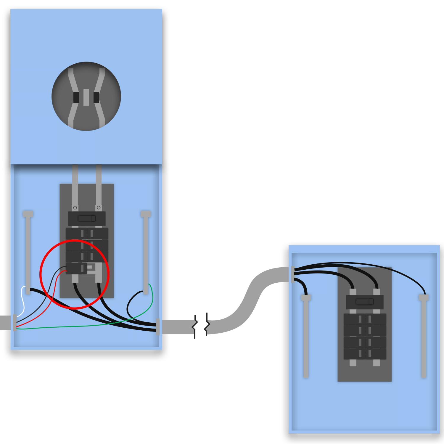
Solar lands on a backfed breaker in the meter-main COMBO bus, with an existing downstream feedthrough panel (with its own main breaker) carrying the dwelling loads. The 120% allowance applies to the COMBO busbar where the PV breaker actually lands: (combo main OCPD) + (PV breaker) ≤ 1.20 × combo busbar. The downstream feedthrough panel is untouched, it keeps its own main and is fed normally; it is not where solar interconnects, so its busbar is not part of the 120% calc here. The PV breaker enters opposite the combo main under a "DO NOT RELOCATE" label.
Backfeed-breaker connection on a meter-main combo bus with an existing, unchanged downstream feedthrough panel. 120% applies to the COMBO bus where the PV breaker lands: combo main + PV breaker ≤ 1.20 × combo busbar.
- 705.12(B)(2): 120% busbar allowance (Article 705 reorganized in 2023)
- 705.12(B)(2)(2)(c): opposite-end placement + label (renumbered)
- 690.8, 408.36, 250.122: unchanged in concept
- 705.12(B)(3)(2): 120% busbar allowance on the meter-main combo bus
- 690.8(A)/(B): PV breaker ≥ 125% of inverter output current
- 408.36: backfed breaker on the combo panelboard busbar
- 705.12(B)(2)(3)(b): "DO NOT RELOCATE" label; PV breaker at the opposite end of the combo bus
- 250.122: EGC sizing
- PV breaker MUST sit at the opposite end of the combo bus from the combo main, under a permanent "DO NOT RELOCATE THIS OVERCURRENT DEVICE" label.
- The 120% calc applies to the METER-MAIN COMBO busbar (where the PV breaker lands), NOT the downstream feedthrough panel bus.
- The existing downstream feedthrough panel keeps its own main and is unchanged by this interconnection.
Backfeed Breaker - New FeedthroughNEC 705.12(B)(3)(2)
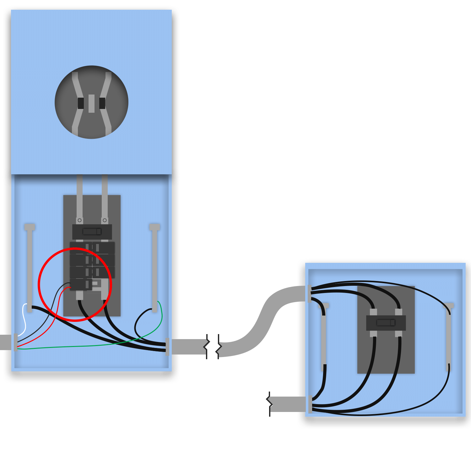
Solar lands on a backfed breaker in the meter-main COMBO bus, and a NEW downstream feedthrough panel (with its own main breaker) is installed to host the dwelling loads. The 120% allowance applies to the COMBO busbar where the PV breaker lands: (combo main OCPD) + (PV breaker) ≤ 1.20 × combo busbar. The new feedthrough panel is a downstream sub-distribution panel, the service N-G bond and grounding electrode stay at the meter-main combo (250.24(A)(5)); the new panel is fed with a 4-wire feeder and a separate EGC, NOT re-bonded. The new panel + its main are NEW equipment. The PV breaker enters opposite the combo main under a "DO NOT RELOCATE" label.
Backfeed-breaker connection on a meter-main combo bus with a NEWLY installed downstream feedthrough panel (own main). 120% applies to the COMBO bus; the new panel is a sub-panel (no re-bond).
- 705.12(B)(2): 120% busbar allowance (Article 705 reorganized in 2023)
- 705.12(B)(2)(2)(c): opposite-end placement + label (renumbered)
- 690.8, 408.36, 250.24(A)(5), 250.122: unchanged in concept
- 705.12(B)(3)(2): 120% busbar allowance on the meter-main combo bus
- 690.8(A)/(B): PV breaker ≥ 125% of inverter output current
- 408.36: backfed breaker on the combo bus; new panel main provides its own OCPD
- 250.24(A)(5): service N-G bond + GES stay at the combo; the new downstream panel is NOT re-bonded
- 705.12(B)(2)(3)(b): "DO NOT RELOCATE" label; PV breaker at the opposite end of the combo bus
- 250.122: EGC sizing
- PV breaker MUST sit at the opposite end of the combo bus from the combo main, under a permanent "DO NOT RELOCATE THIS OVERCURRENT DEVICE" label.
- The 120% calc applies to the METER-MAIN COMBO busbar (where the PV breaker lands), NOT the new feedthrough panel bus.
- NEW feedthrough panel + its main are NEW equipment; the bond + GES stay at the combo (250.24(A)(5)), the new panel is a sub-panel fed by a 4-wire feeder, not re-bonded.
Backfeed Breaker - Meter-Main with Derate (feedthrough)NEC 705.12(B)(3)(2)
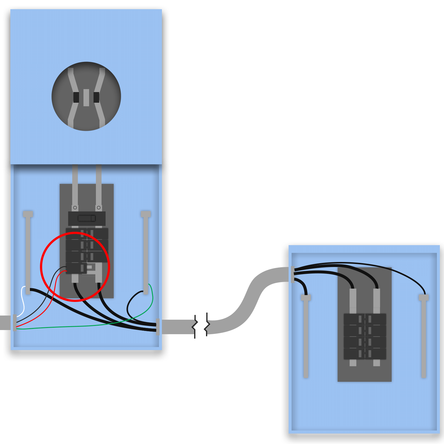
Solar lands on a backfed breaker in the meter-main COMBO bus with an existing downstream feedthrough panel, and the combo main breaker is DERATED so the 120% sum clears. When (combo main OCPD) + (PV breaker) > 1.20 × combo busbar, swapping the combo main to a smaller standard size shrinks the first term until the inequality passes. The derated combo main still protects the busbar and conductors (240.4) and must still serve the dwelling's Article 220 calculated load. The PV breaker enters opposite the combo main under a "DO NOT RELOCATE" label; the existing downstream feedthrough panel is fed normally.
Backfeed-breaker connection on a meter-main combo bus (existing downstream feedthrough panel) with the combo main derated so (derated main + PV breaker) ≤ 1.20 × combo busbar. Derated main must still protect conductors and serve the load.
- 705.12(B)(2): 120% busbar allowance (Article 705 reorganized in 2023)
- 705.12(B)(2)(2)(c): opposite-end placement + label (renumbered)
- 240.4, 690.8, 408.36, 250.122: unchanged in concept
- 705.12(B)(3)(2): 120% busbar allowance on the combo bus, satisfied by derating the main
- 240.4: the derated combo main must still protect the busbar and service conductors
- 690.8(A)/(B): PV breaker ≥ 125% of inverter output current
- 408.36: backfed breaker on the combo panelboard busbar
- 705.12(B)(2)(3)(b): "DO NOT RELOCATE" label; PV breaker at the opposite end of the combo bus
- 250.122: EGC sizing
- PV breaker MUST sit at the opposite end of the combo bus from the combo main, under a permanent "DO NOT RELOCATE THIS OVERCURRENT DEVICE" label.
- The 120% calc applies to the METER-MAIN COMBO busbar (where the PV breaker lands), NOT the downstream feedthrough panel bus; the derate reduces the combo main term.
- The derated combo main must still PROTECT the conductors (240.4) AND still serve the Article 220 calculated load, do not derate below the actual demand.
Backfeed Breaker - Meter-Main with Feedthrough and DerateNEC 705.12(B)(3)(2)
Solar lands on a backfed breaker in the meter-main COMBO bus, the combo main is DERATED to clear the 120% sum, and an existing downstream feedthrough panel with its own main breaker carries the loads. When (combo main OCPD) + (PV breaker) > 1.20 × combo busbar, swapping the combo main to a smaller standard size shrinks the first term until the inequality passes. The derated combo main still protects the busbar and conductors (240.4) and must still serve the Article 220 calculated load. The downstream feedthrough panel keeps its own main and is fed normally; the PV breaker enters opposite the combo main under a "DO NOT RELOCATE" label.
Backfeed-breaker connection on a meter-main combo bus (existing downstream feedthrough panel with its own main) with the combo main derated so (derated main + PV breaker) ≤ 1.20 × combo busbar.
- 705.12(B)(2): 120% busbar allowance (Article 705 reorganized in 2023)
- 705.12(B)(2)(2)(c): opposite-end placement + label (renumbered)
- 240.4, 690.8, 408.36, 250.122: unchanged in concept
- 705.12(B)(3)(2): 120% busbar allowance on the combo bus, satisfied by derating the main
- 240.4: the derated combo main must still protect the busbar and service conductors
- 690.8(A)/(B): PV breaker ≥ 125% of inverter output current
- 408.36: backfed breaker on the combo bus; downstream panel main provides its own OCPD
- 705.12(B)(2)(3)(b): "DO NOT RELOCATE" label; PV breaker at the opposite end of the combo bus
- 250.122: EGC sizing
- PV breaker MUST sit at the opposite end of the combo bus from the combo main, under a permanent "DO NOT RELOCATE THIS OVERCURRENT DEVICE" label.
- The 120% calc applies to the METER-MAIN COMBO busbar (where the PV breaker lands), NOT the downstream feedthrough panel bus; the derate reduces the combo main term.
- The derated combo main must still PROTECT the conductors (240.4) AND still serve the Article 220 calculated load. The existing downstream feedthrough panel keeps its own main, unchanged.
Backfeed Breaker - In Feedthrough PanelNEC 705.12(B)(3)(2)
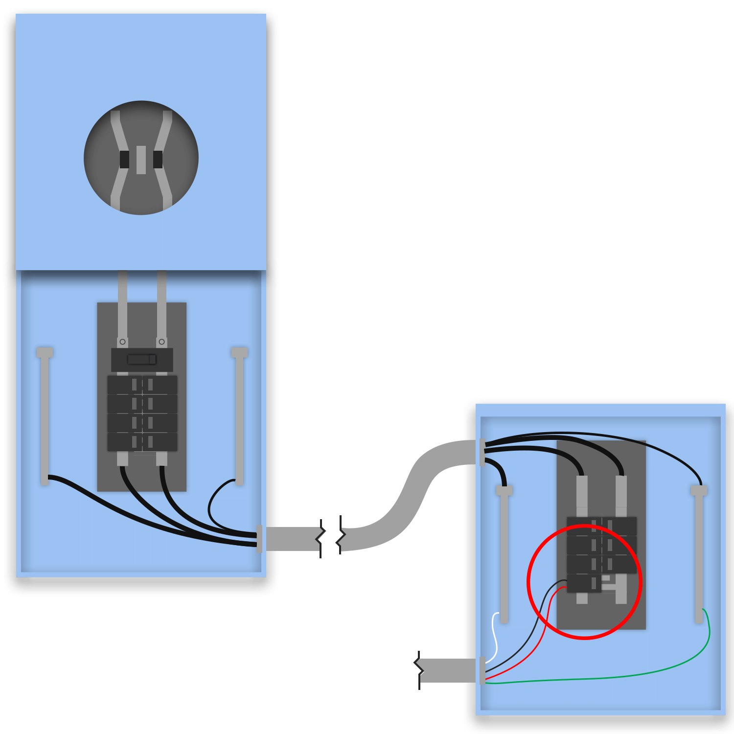
Solar lands on a backfed breaker in a downstream MLO (main-lug-only) FEEDTHROUGH panel rather than the meter-main combo. The 120% allowance applies to the FEEDTHROUGH panel busbar, but an MLO panel has no main breaker of its own to form the first term, so the bounding OCPD is the upstream device protecting the feed to that panel (the combo main or the feedthrough feeder breaker). The calc is (upstream feed OCPD) + (PV breaker) ≤ 1.20 × feedthrough busbar. The PV breaker is sized at the next standard size ≥ 125% × inverter output (690.8) and lands at the opposite end of the feedthrough bus from the feed-in lugs under a "DO NOT RELOCATE" label.
Backfeed-breaker connection on a downstream MLO feedthrough panel busbar. 120% applies to the FEEDTHROUGH bus, bounded by the upstream feed OCPD: (feed OCPD) + (PV breaker) ≤ 1.20 × feedthrough busbar.
- 705.12(B)(2): 120% busbar allowance (Article 705 reorganized in 2023)
- 705.12(B)(2)(2)(c): opposite-end placement + label (renumbered)
- 690.8, 408.36, 250.122: unchanged in concept
- 705.12(B)(3)(2): 120% busbar allowance on the feedthrough panel bus
- 690.8(A)/(B): PV breaker ≥ 125% of inverter output current
- 408.36: backfed breaker on the feedthrough panelboard busbar (MLO panel protected by the upstream feed OCPD)
- 705.12(B)(2)(3)(b): "DO NOT RELOCATE" label; PV breaker opposite the feed-in end of the bus
- 250.122: EGC sizing
- PV breaker MUST sit at the opposite end of the feedthrough bus from the feed-in lugs, under a permanent "DO NOT RELOCATE THIS OVERCURRENT DEVICE" label.
- The 120% calc applies to the DOWNSTREAM FEEDTHROUGH panel busbar, NOT the meter-main combo bus. The MLO panel has no main, so the upstream feed OCPD forms the first term.
- An MLO feedthrough panel has no main breaker of its own; the device protecting the feed to the panel bounds the calc.
Backfeed Breaker - Feedthrough with MainNEC 705.12(B)(3)(2)
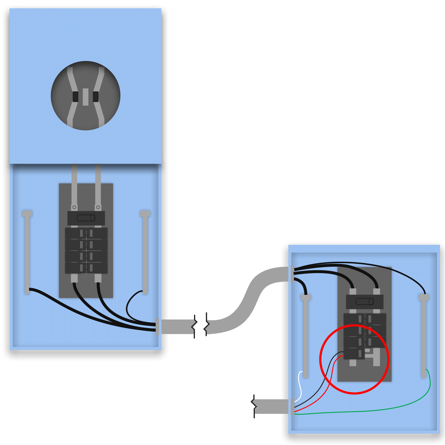
Solar lands on a backfed breaker in a downstream FEEDTHROUGH panel that has its OWN main breaker. Because the panel has a main, the 120% calc is the clean classic form on the FEEDTHROUGH busbar: (feedthrough panel main OCPD) + (PV breaker) ≤ 1.20 × feedthrough busbar. The PV breaker is sized at the next standard size ≥ 125% × inverter output (690.8) and lands at the opposite end of the feedthrough bus from its main under a "DO NOT RELOCATE" label. The upstream meter-main combo is not where solar interconnects, so its bus is not part of this calc.
Backfeed-breaker connection on a downstream feedthrough panel that has its own main. 120% applies to the FEEDTHROUGH bus, bounded by the feedthrough panel main: (panel main + PV breaker) ≤ 1.20 × feedthrough busbar.
- 705.12(B)(2): 120% busbar allowance (Article 705 reorganized in 2023)
- 705.12(B)(2)(2)(c): opposite-end placement + label (renumbered)
- 690.8, 408.36, 250.122: unchanged in concept
- 705.12(B)(3)(2): 120% busbar allowance on the feedthrough panel bus (bounded by its own main)
- 690.8(A)/(B): PV breaker ≥ 125% of inverter output current
- 408.36: backfed breaker on the feedthrough panelboard busbar
- 705.12(B)(2)(3)(b): "DO NOT RELOCATE" label; PV breaker at the opposite end of the bus from the panel main
- 250.122: EGC sizing
- PV breaker MUST sit at the opposite end of the feedthrough bus from the panel main, under a permanent "DO NOT RELOCATE THIS OVERCURRENT DEVICE" label.
- The 120% calc applies to the DOWNSTREAM FEEDTHROUGH panel busbar, bounded by that panel's OWN main, NOT the meter-main combo bus.
- Because the feedthrough panel has a main, the calc is the classic (panel main + PV breaker) ≤ 1.20 × busbar.
Backfeed Breaker - Feedthrough with DerateNEC 705.12(B)(3)(2)
Solar lands on a backfed breaker in a downstream MLO feedthrough panel, and the UPSTREAM main breaker (the device feeding that panel) is DERATED so the 120% sum clears on the feedthrough bus. An MLO panel has no main of its own, so the upstream feed OCPD forms the first term: (upstream feed OCPD) + (PV breaker) ≤ 1.20 × feedthrough busbar, derating the upstream device shrinks the first term until it passes. The derated upstream main still protects the feedthrough conductors and bus (240.4) and must still serve the Article 220 calculated load. The PV breaker lands opposite the feed-in end under a "DO NOT RELOCATE" label.
Backfeed-breaker connection on a downstream MLO feedthrough panel with the upstream main derated so (derated upstream OCPD + PV breaker) ≤ 1.20 × feedthrough busbar. Derated main must still protect conductors and serve the load.
- 705.12(B)(2): 120% busbar allowance (Article 705 reorganized in 2023)
- 705.12(B)(2)(2)(c): opposite-end placement + label (renumbered)
- 240.4, 690.8, 408.36, 250.122: unchanged in concept
- 705.12(B)(3)(2): 120% busbar allowance on the feedthrough bus, satisfied by derating the upstream main
- 240.4: the derated upstream main must still protect the feedthrough conductors and bus
- 690.8(A)/(B): PV breaker ≥ 125% of inverter output current
- 408.36: backfed breaker on the feedthrough panelboard busbar (MLO panel)
- 705.12(B)(2)(3)(b): "DO NOT RELOCATE" label; PV breaker opposite the feed-in end of the bus
- 250.122: EGC sizing
- PV breaker MUST sit at the opposite end of the feedthrough bus from the feed-in lugs, under a permanent "DO NOT RELOCATE THIS OVERCURRENT DEVICE" label.
- The 120% calc applies to the DOWNSTREAM MLO FEEDTHROUGH panel busbar; the MLO panel has no main, so the derated UPSTREAM feed OCPD forms the first term.
- The derated upstream main must still PROTECT the feedthrough conductors (240.4) AND still serve the Article 220 calculated load, do not derate below the actual demand.
Backfeed Breaker - Feedthrough with Main and DerateNEC 705.12(B)(3)(2)
Solar lands on a backfed breaker in a downstream feedthrough panel that has its OWN main, and the UPSTREAM main breaker (feeding that panel) is DERATED. The 120% calc itself is the classic form on the feedthrough bus: (feedthrough panel main OCPD) + (PV breaker) ≤ 1.20 × feedthrough busbar. The upstream derate is applied so the upstream feeder/service side stays coordinated, the derated upstream device still protects the feedthrough conductors (240.4) and must still serve the Article 220 calculated load. The PV breaker lands at the opposite end of the feedthrough bus from the panel's main under a "DO NOT RELOCATE" label.
Backfeed-breaker connection on a downstream feedthrough panel with its own main, upstream main derated. 120% applies to the FEEDTHROUGH bus bounded by the panel main; the upstream derate keeps the feeder coordinated and must still protect conductors + serve the load.
- 705.12(B)(2): 120% busbar allowance (Article 705 reorganized in 2023)
- 705.12(B)(2)(2)(c): opposite-end placement + label (renumbered)
- 240.4, 690.8, 408.36, 250.122: unchanged in concept
- 705.12(B)(3)(2): 120% busbar allowance on the feedthrough bus (bounded by the panel main)
- 240.4: the derated upstream main must still protect the feedthrough conductors
- 690.8(A)/(B): PV breaker ≥ 125% of inverter output current
- 408.36: backfed breaker on the feedthrough panelboard busbar
- 705.12(B)(2)(3)(b): "DO NOT RELOCATE" label; PV breaker at the opposite end of the bus from the panel main
- 250.122: EGC sizing
- PV breaker MUST sit at the opposite end of the feedthrough bus from the panel main, under a permanent "DO NOT RELOCATE THIS OVERCURRENT DEVICE" label.
- The 120% calc applies to the DOWNSTREAM FEEDTHROUGH panel busbar, bounded by that panel's own main, NOT the upstream bus.
- The derated upstream main must still PROTECT the feedthrough conductors (240.4) AND still serve the Article 220 calculated load, do not derate below the actual demand.
Backfeed Breaker - Separate DisconnectNEC 705.12(B)(3)(2)
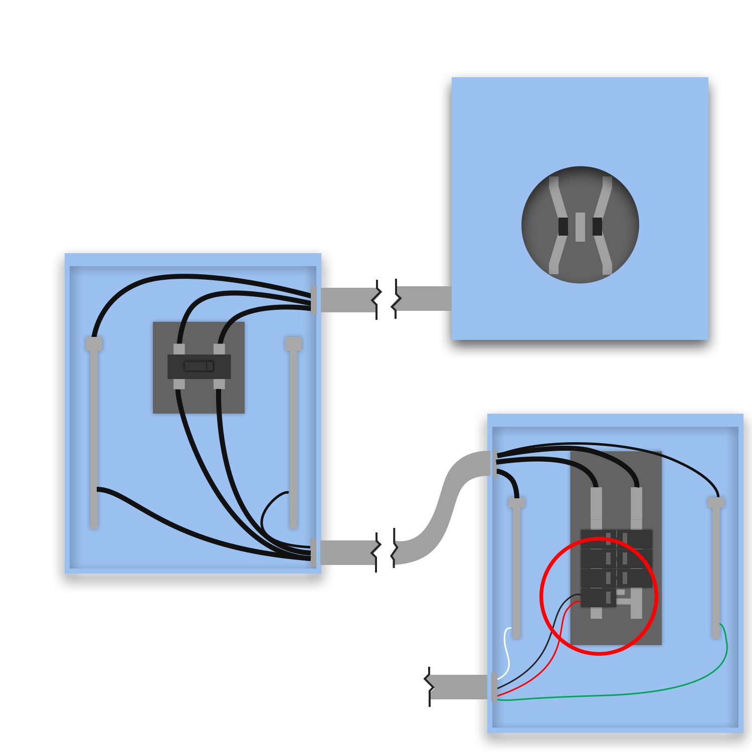
On a Separate Disconnect service (a standalone service disconnect ahead of the distribution panel), solar lands on a backfed breaker in the downstream feedthrough panel. The 120% allowance applies to that FEEDTHROUGH panel busbar, bounded by the OCPD protecting the feed to it (the upstream service disconnect main, or the panel's own main if present): (feed OCPD) + (PV breaker) ≤ 1.20 × feedthrough busbar. The PV breaker is sized at the next standard size ≥ 125% × inverter output (690.8) and lands at the opposite end of the feedthrough bus under a "DO NOT RELOCATE" label.
Backfeed-breaker connection on the downstream feedthrough panel in a Separate Disconnect service. 120% applies to the FEEDTHROUGH bus, bounded by the upstream feed OCPD: (feed OCPD + PV breaker) ≤ 1.20 × feedthrough busbar.
- 705.12(B)(2): 120% busbar allowance (Article 705 reorganized in 2023)
- 705.12(B)(2)(2)(c): opposite-end placement + label (renumbered)
- 690.8, 408.36, 250.122: unchanged in concept
- 705.12(B)(3)(2): 120% busbar allowance on the feedthrough panel bus
- 690.8(A)/(B): PV breaker ≥ 125% of inverter output current
- 408.36: backfed breaker on the feedthrough panelboard busbar
- 705.12(B)(2)(3)(b): "DO NOT RELOCATE" label; PV breaker opposite the feed-in end of the bus
- 250.122: EGC sizing
- PV breaker MUST sit at the opposite end of the feedthrough bus from the feed-in end, under a permanent "DO NOT RELOCATE THIS OVERCURRENT DEVICE" label.
- The 120% calc applies to the DOWNSTREAM FEEDTHROUGH panel busbar in this Separate Disconnect topology, NOT the standalone service disconnect.
- The bounding OCPD is the device feeding the panel (the service disconnect main, or the panel's own main if it has one).
Backfeed Breaker with Derate - Separate DisconnectNEC 705.12(B)(3)(2)
On a Separate Disconnect service, solar lands on a backfed breaker in the downstream feedthrough panel, and the UPSTREAM service main disconnect is DERATED so the 120% sum clears on the feedthrough bus. The feedthrough bus is bounded by the OCPD feeding it; derating the upstream disconnect main shrinks the first term of (feed OCPD) + (PV breaker) ≤ 1.20 × feedthrough busbar until it passes. The derated disconnect main still protects the feedthrough conductors and bus (240.4) and must still serve the Article 220 calculated load. The PV breaker lands at the opposite end of the feedthrough bus under a "DO NOT RELOCATE" label.
Backfeed-breaker connection on the downstream feedthrough panel (Separate Disconnect service) with the upstream service disconnect derated so (derated feed OCPD + PV breaker) ≤ 1.20 × feedthrough busbar.
- 705.12(B)(2): 120% busbar allowance (Article 705 reorganized in 2023)
- 705.12(B)(2)(2)(c): opposite-end placement + label (renumbered)
- 240.4, 690.8, 408.36, 250.122: unchanged in concept
- 705.12(B)(3)(2): 120% busbar allowance on the feedthrough bus, satisfied by derating the upstream disconnect
- 240.4: the derated upstream disconnect main must still protect the feedthrough conductors and bus
- 690.8(A)/(B): PV breaker ≥ 125% of inverter output current
- 408.36: backfed breaker on the feedthrough panelboard busbar
- 705.12(B)(2)(3)(b): "DO NOT RELOCATE" label; PV breaker opposite the feed-in end of the bus
- 250.122: EGC sizing
- PV breaker MUST sit at the opposite end of the feedthrough bus from the feed-in end, under a permanent "DO NOT RELOCATE THIS OVERCURRENT DEVICE" label.
- The 120% calc applies to the DOWNSTREAM FEEDTHROUGH panel busbar; the derate reduces the upstream feed OCPD term that bounds it.
- The derated upstream disconnect main must still PROTECT the feedthrough conductors (240.4) AND still serve the Article 220 calculated load, do not derate below the actual demand.
Backfeed Breaker - Feedthrough Panel (Meter-Main Disconnect)NEC 705.12(B)(3)(2)
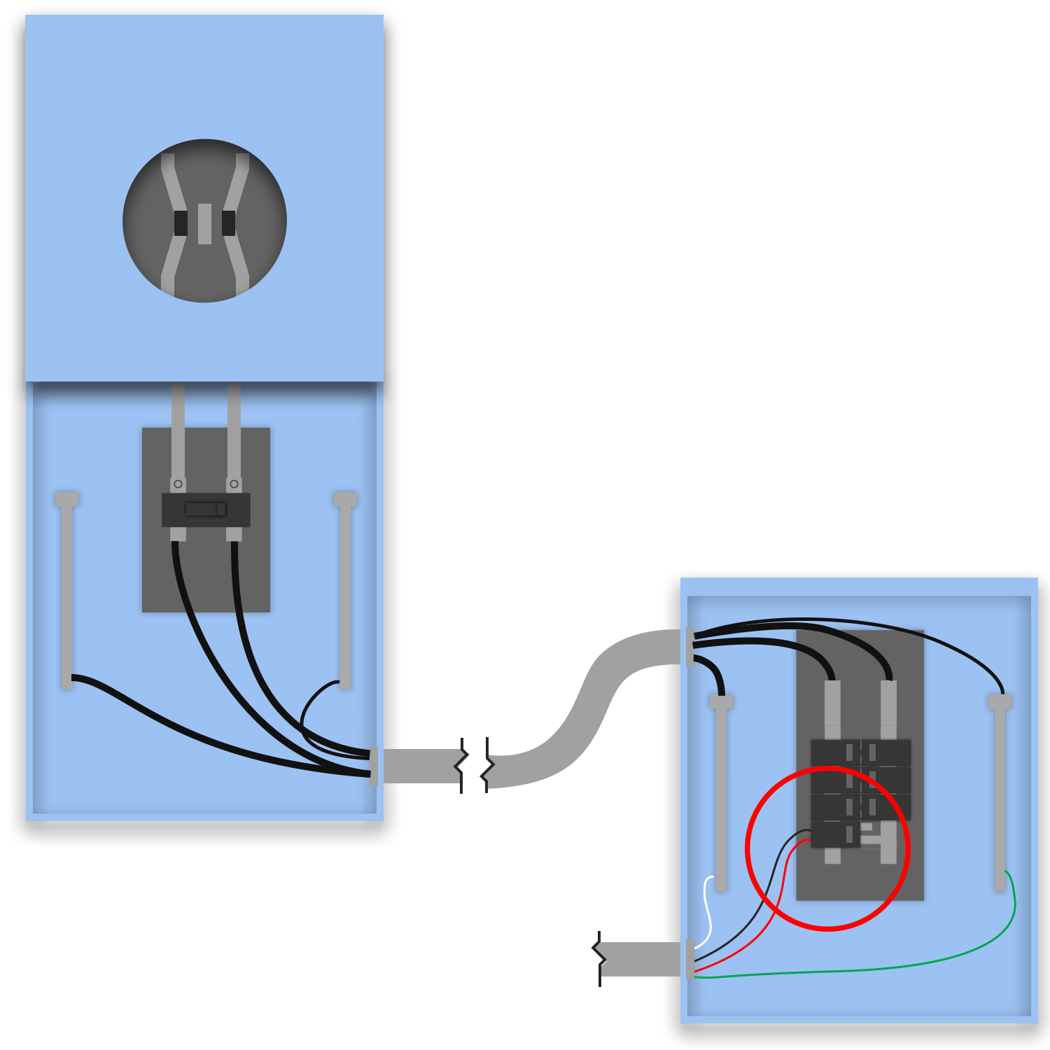
On a meter-main DISCONNECT service (combined meter + service main breaker + N-G bond + GES, no load distribution of its own), solar lands on a backfed breaker in the downstream MLO feedthrough panel that the disconnect feeds. The 120% allowance applies to that FEEDTHROUGH panel busbar, and since it is MLO with no main of its own, the bounding OCPD is the meter-main disconnect's main feeding it: (disconnect main OCPD) + (PV breaker) ≤ 1.20 × feedthrough busbar. The PV breaker is sized at the next standard size ≥ 125% × inverter output (690.8) and lands at the opposite end of the feedthrough bus from the feed-in lugs under a "DO NOT RELOCATE" label.
Backfeed-breaker connection on a downstream MLO feedthrough panel fed from a meter-main disconnect. 120% applies to the FEEDTHROUGH bus, bounded by the disconnect main: (disconnect main + PV breaker) ≤ 1.20 × feedthrough busbar.
- 705.12(B)(2): 120% busbar allowance (Article 705 reorganized in 2023)
- 705.12(B)(2)(2)(c): opposite-end placement + label (renumbered)
- 690.8, 408.36, 250.122: unchanged in concept
- 705.12(B)(3)(2): 120% busbar allowance on the feedthrough panel bus
- 690.8(A)/(B): PV breaker ≥ 125% of inverter output current
- 408.36: backfed breaker on the feedthrough panelboard busbar (MLO panel protected by the disconnect main)
- 705.12(B)(2)(3)(b): "DO NOT RELOCATE" label; PV breaker opposite the feed-in end of the bus
- 250.122: EGC sizing
- PV breaker MUST sit at the opposite end of the feedthrough bus from the feed-in lugs, under a permanent "DO NOT RELOCATE THIS OVERCURRENT DEVICE" label.
- The 120% calc applies to the DOWNSTREAM MLO FEEDTHROUGH panel busbar, NOT the meter-main disconnect. The MLO panel has no main, so the disconnect main forms the first term.
- The meter-main disconnect remains the service disconnect (N-G bond + GES); the downstream feedthrough panel is not re-bonded.
Backfeed Breaker - Feedthrough with Main (Meter-Main Disconnect)NEC 705.12(B)(3)(2)
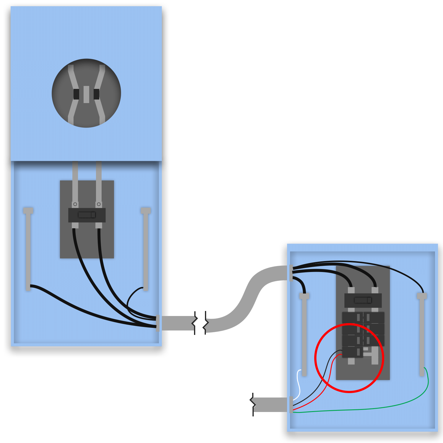
On a meter-main DISCONNECT service, solar lands on a backfed breaker in the downstream feedthrough panel that has its OWN main breaker. Because the panel has a main, the 120% calc is the clean classic form on the FEEDTHROUGH busbar: (feedthrough panel main OCPD) + (PV breaker) ≤ 1.20 × feedthrough busbar. The PV breaker is sized at the next standard size ≥ 125% × inverter output (690.8) and lands at the opposite end of the feedthrough bus from its main under a "DO NOT RELOCATE" label. The meter-main disconnect upstream is not the interconnection point, so its rating does not enter this calc.
Backfeed-breaker connection on a downstream feedthrough panel (own main) fed from a meter-main disconnect. 120% applies to the FEEDTHROUGH bus bounded by the panel main: (panel main + PV breaker) ≤ 1.20 × feedthrough busbar.
- 705.12(B)(2): 120% busbar allowance (Article 705 reorganized in 2023)
- 705.12(B)(2)(2)(c): opposite-end placement + label (renumbered)
- 690.8, 408.36, 250.122: unchanged in concept
- 705.12(B)(3)(2): 120% busbar allowance on the feedthrough panel bus (bounded by its own main)
- 690.8(A)/(B): PV breaker ≥ 125% of inverter output current
- 408.36: backfed breaker on the feedthrough panelboard busbar
- 705.12(B)(2)(3)(b): "DO NOT RELOCATE" label; PV breaker at the opposite end of the bus from the panel main
- 250.122: EGC sizing
- PV breaker MUST sit at the opposite end of the feedthrough bus from the panel main, under a permanent "DO NOT RELOCATE THIS OVERCURRENT DEVICE" label.
- The 120% calc applies to the DOWNSTREAM FEEDTHROUGH panel busbar, bounded by that panel's OWN main, NOT the meter-main disconnect.
- The meter-main disconnect remains the service disconnect (N-G bond + GES); the feedthrough panel keeps its own main and is not re-bonded.
Backfeed Breaker with Derate - Feedthrough Panel (Meter-Main Disconnect)NEC 705.12(B)(3)(2)
On a meter-main DISCONNECT service, solar lands on a backfed breaker in the downstream MLO feedthrough panel, and the meter-main disconnect's main breaker is DERATED so the 120% sum clears on the feedthrough bus. The MLO panel has no main of its own, so the disconnect main forms the first term: (disconnect main OCPD) + (PV breaker) ≤ 1.20 × feedthrough busbar, derating the disconnect main shrinks the first term until it passes. The derated disconnect main still protects the feedthrough conductors and bus (240.4) and must still serve the Article 220 calculated load. The PV breaker lands at the opposite end of the feedthrough bus under a "DO NOT RELOCATE" label.
Backfeed-breaker connection on a downstream MLO feedthrough panel fed from a meter-main disconnect, with the disconnect main derated so (derated disconnect main + PV breaker) ≤ 1.20 × feedthrough busbar.
- 705.12(B)(2): 120% busbar allowance (Article 705 reorganized in 2023)
- 705.12(B)(2)(2)(c): opposite-end placement + label (renumbered)
- 240.4, 690.8, 408.36, 250.122: unchanged in concept
- 705.12(B)(3)(2): 120% busbar allowance on the feedthrough bus, satisfied by derating the disconnect main
- 240.4: the derated disconnect main must still protect the feedthrough conductors and bus
- 690.8(A)/(B): PV breaker ≥ 125% of inverter output current
- 408.36: backfed breaker on the feedthrough panelboard busbar (MLO panel)
- 705.12(B)(2)(3)(b): "DO NOT RELOCATE" label; PV breaker opposite the feed-in end of the bus
- 250.122: EGC sizing
- PV breaker MUST sit at the opposite end of the feedthrough bus from the feed-in lugs, under a permanent "DO NOT RELOCATE THIS OVERCURRENT DEVICE" label.
- The 120% calc applies to the DOWNSTREAM MLO FEEDTHROUGH panel busbar; the MLO panel has no main, so the derated disconnect main forms the first term.
- The derated meter-main disconnect main must still PROTECT the feedthrough conductors (240.4) AND still serve the Article 220 calculated load, do not derate below the actual demand.
Backfeed Breaker with Derate - Feedthrough w/ Main (Meter-Main Disconnect)NEC 705.12(B)(3)(2)
On a meter-main DISCONNECT service, solar lands on a backfed breaker in the downstream feedthrough panel that has its OWN main, and the meter-main disconnect main is DERATED. The 120% calc itself is the classic form on the feedthrough bus: (feedthrough panel main OCPD) + (PV breaker) ≤ 1.20 × feedthrough busbar. The upstream derate keeps the meter-main disconnect coordinated with the feeder, the derated disconnect main still protects the feedthrough conductors (240.4) and must still serve the Article 220 calculated load. The PV breaker lands at the opposite end of the feedthrough bus from the panel's main under a "DO NOT RELOCATE" label.
Backfeed-breaker connection on a downstream feedthrough panel (own main) fed from a meter-main disconnect, with the disconnect main derated. 120% applies to the FEEDTHROUGH bus bounded by the panel main; the upstream derate keeps the feeder coordinated and must still protect conductors + serve the load.
- 705.12(B)(2): 120% busbar allowance (Article 705 reorganized in 2023)
- 705.12(B)(2)(2)(c): opposite-end placement + label (renumbered)
- 240.4, 690.8, 408.36, 250.122: unchanged in concept
- 705.12(B)(3)(2): 120% busbar allowance on the feedthrough bus (bounded by the panel main)
- 240.4: the derated disconnect main must still protect the feedthrough conductors
- 690.8(A)/(B): PV breaker ≥ 125% of inverter output current
- 408.36: backfed breaker on the feedthrough panelboard busbar
- 705.12(B)(2)(3)(b): "DO NOT RELOCATE" label; PV breaker at the opposite end of the bus from the panel main
- 250.122: EGC sizing
- PV breaker MUST sit at the opposite end of the feedthrough bus from the panel main, under a permanent "DO NOT RELOCATE THIS OVERCURRENT DEVICE" label.
- The 120% calc applies to the DOWNSTREAM FEEDTHROUGH panel busbar, bounded by that panel's own main, NOT the meter-main disconnect bus.
- The derated meter-main disconnect main must still PROTECT the feedthrough conductors (240.4) AND still serve the Article 220 calculated load, do not derate below the actual demand.
Sum Rule: Load-Side
The sum of all overcurrent devices supplying the busbar (including the PV breaker) stays within the busbar rating. Used when the 120% allowance does not fit.
Backfeed with Sum Rule - Meter-MainNEC 705.12(B)(3)(3)
Backfeed breaker on the meter-main combo bus, qualified by the SUM RULE instead of the 120% rule. Where the 120% rule allows main + PV ≤ 1.20 × busbar, the sum rule is tighter: the sum of ALL overcurrent devices supplying the busbar (main + PV) must not exceed the busbar ampere rating, no 20% headroom. Used when the 120% math fails but the conductors/busbar still have margin at 100%. Its tradeoff cuts both ways: tighter ampere budget, but it does NOT carry the 120% rule's opposite-end placement requirement, so the PV breaker can sit anywhere on the bus. The existing downstream feedthrough panel (with its own main) is unchanged.
Backfeed breaker on the meter-main combo busbar qualified by the SUM RULE: main + PV breaker ≤ busbar ampere rating (no 120% headroom). Chosen when 120% fails; trades a tighter ampere budget for no opposite-end placement constraint.
- 705.12(B)(3): sum rule (Article 705 reorganized in 2023)
- 690.8, 408.36, 250.122: unchanged in concept
- 705.12(B)(3)(3): sum rule: Σ(OCPD supplying the busbar) ≤ busbar ampere rating
- 690.8(A)/(B): PV breaker ≥ 125% of inverter output current
- 408.36: backfed breaker on the combo panelboard busbar
- 250.122: EGC sizing
- Sum rule is TIGHTER than 120%: main + PV ≤ busbar (no ×1.20). Use only when the 120% rule fails and the bus still has room at 100%.
- Unlike the 120% rule, the sum rule does NOT require the PV breaker at the opposite end of the bus or a "DO NOT RELOCATE" label, placement is unconstrained.
- Applies to the meter-main COMBO busbar; the existing downstream feedthrough panel is unchanged.
Backfeed with Sum Rule - New FeedthroughNEC 705.12(B)(3)(3)
Same sum-rule backfeed on the meter-main combo bus as Backfeed with Sum Rule - Meter-Main, but a NEW downstream feedthrough panel (with its own main) is installed as part of the scope. The sum rule still governs the combo busbar (main + PV ≤ busbar, no 120% headroom); the new feedthrough panel is added downstream as a separate enclosure to host the dwelling loads. The new panel + its main are NEW equipment; the service-entrance N-G bond stays at the combo (250.24(A)(5)).
Sum-rule backfeed on the meter-main combo busbar (main + PV ≤ busbar) with a NEW downstream feedthrough panel installed. Sum rule on the combo bus; new panel is a separate downstream enclosure.
- 705.12(B)(3): sum rule (Article 705 reorganized in 2023)
- 690.8, 408.36, 250.24(A)(5), 250.122: unchanged in concept
- 705.12(B)(3)(3): sum rule: Σ(OCPD supplying the busbar) ≤ busbar ampere rating
- 690.8(A)/(B): PV breaker ≥ 125% of inverter output current
- 408.36: backfed breaker on the combo panelboard busbar
- 250.24(A)(5): service N-G bond stays at the combo; new downstream panel NOT re-bonded · 250.122: EGC
- Sum rule (no ×1.20) on the combo busbar, same tighter budget + no opposite-end placement requirement as Backfeed with Sum Rule - Meter-Main.
- NEW feedthrough panel + its main are NEW equipment; it is a sub-distribution panel, no N-G bond (250.24(A)(5)), 4-wire feeder with separate EGC.
Load Tap with Sum RuleNEC 705.12(B)(3)(3)
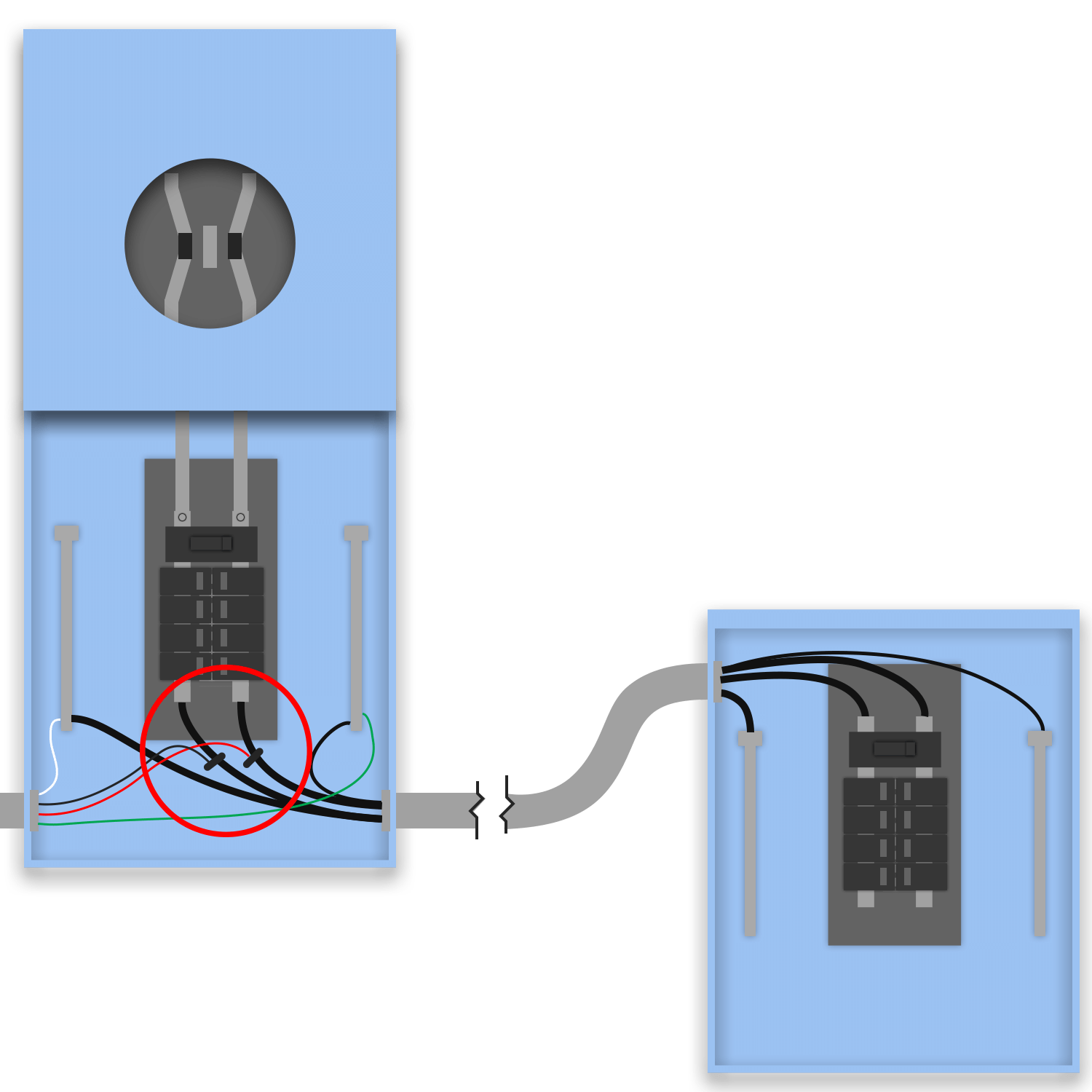
Load-side tap on an existing downstream feedthrough panel (with its own main), qualified by the SUM RULE on that panel's busbar. The tap brings the PV source onto the feedthrough panel; the sum of the panel's main + the PV contribution must stay within the panel busbar rating (no 120% headroom). This is the sum-rule alternative to Load Side Tap - Feedthrough with Main, chosen when the panel bus can't satisfy the 120% allowance but does hold at 100%. A fused AC disconnect protects the tap conductors (705.12 feed-through + 240.21(B)).
Load-side tap on an existing feedthrough panel (own main) qualified by the SUM RULE on that panel busbar (main + PV ≤ busbar, no 120% headroom). Fused tap disconnect provides tap-conductor OCPD.
- 705.12(B)(3): sum rule (Article 705 reorganized in 2023)
- 705.12(A): load-side feed-through tap
- 240.21(B), 408.36, 250.122: unchanged in concept
- 705.12(B)(3)(3): sum rule on the feedthrough panel busbar: main + PV ≤ busbar ampere rating
- 705.12(B)(2): load-side feed-through tap that brings PV onto the panel
- 240.21(B): fused tap-conductor protection · 408.36: panelboard busbar protection
- 250.122: EGC sizing
- Sum rule on the feedthrough panel busbar (no ×1.20), the alternative to the 120% rule when the bus holds at 100% but not 120%.
- A FUSED AC disconnect is required for the load-side tap (240.21(B)); the tap is on lugs, so no opposite-end / DO-NOT-RELOCATE placement rule applies.
- Existing feedthrough panel with its own main, no added main breaker.
Load Tap with Sum Rule - New FeedthroughNEC 705.12(B)(3)(3)
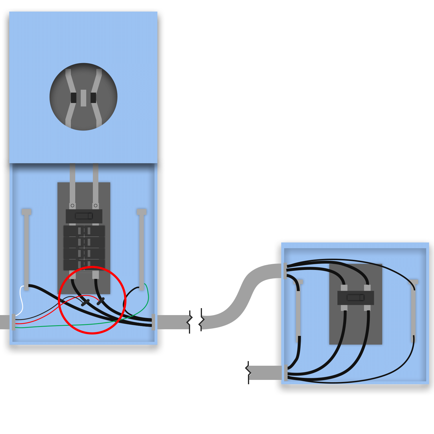
Load-side tap qualified by the SUM RULE, but a NEW feedthrough panel (with its own main) is installed downstream to host the loads. The sum rule governs the new panel's busbar (its main + the tapped PV ≤ busbar, no 120% headroom). Same as Load Tap with Sum Rule but the downstream panel is new equipment rather than existing. A fused AC disconnect protects the tap; the new panel is a sub-distribution panel (no N-G re-bond, 250.24(A)(5)).
Load-side tap with a NEW feedthrough panel (own main), qualified by the SUM RULE on the new panel busbar (main + PV ≤ busbar). New panel is NEW equipment; fused tap disconnect provides tap-conductor OCPD.
- 705.12(B)(3): sum rule (Article 705 reorganized in 2023)
- 705.12(A): load-side feed-through tap
- 240.21(B), 408.36, 250.24(A)(5), 250.122: unchanged in concept
- 705.12(B)(3)(3): sum rule on the new feedthrough panel busbar
- 705.12(B)(2): load-side feed-through tap onto the panel
- 240.21(B): fused tap-conductor protection · 408.36: new panelboard main
- 250.24(A)(5): bond stays at the service; new downstream panel NOT re-bonded · 250.122: EGC
- Sum rule (no ×1.20) on the NEW feedthrough panel busbar, the new-equipment counterpart to Load Tap with Sum Rule.
- NEW feedthrough panel + main are NEW equipment; sub-distribution panel, no N-G bond (250.24(A)(5)), 4-wire feeder + separate EGC.
- Fused AC disconnect required for the tap (240.21(B)).
- SEGMENT SIZING, same as Load Side Tap - New Feedthrough Panel (docs/FEEDTHROUGH_TAP_SIZING.md): tap-to-new-main conductors are NEW wire sized to the new main; the inserted main at the existing downstream conductor is the CONTESTED question (see that entry), the uncontested resolution is a 125A main against a 130A conductor (plain 240.4).
Feed-Through Tap
PV taps the feed-through conductors between a meter-main and a downstream panel, sized per the feeder tap rules.
Load Side Tap - Feedthrough (No Main)NEC 705.12(B)(3)(6)
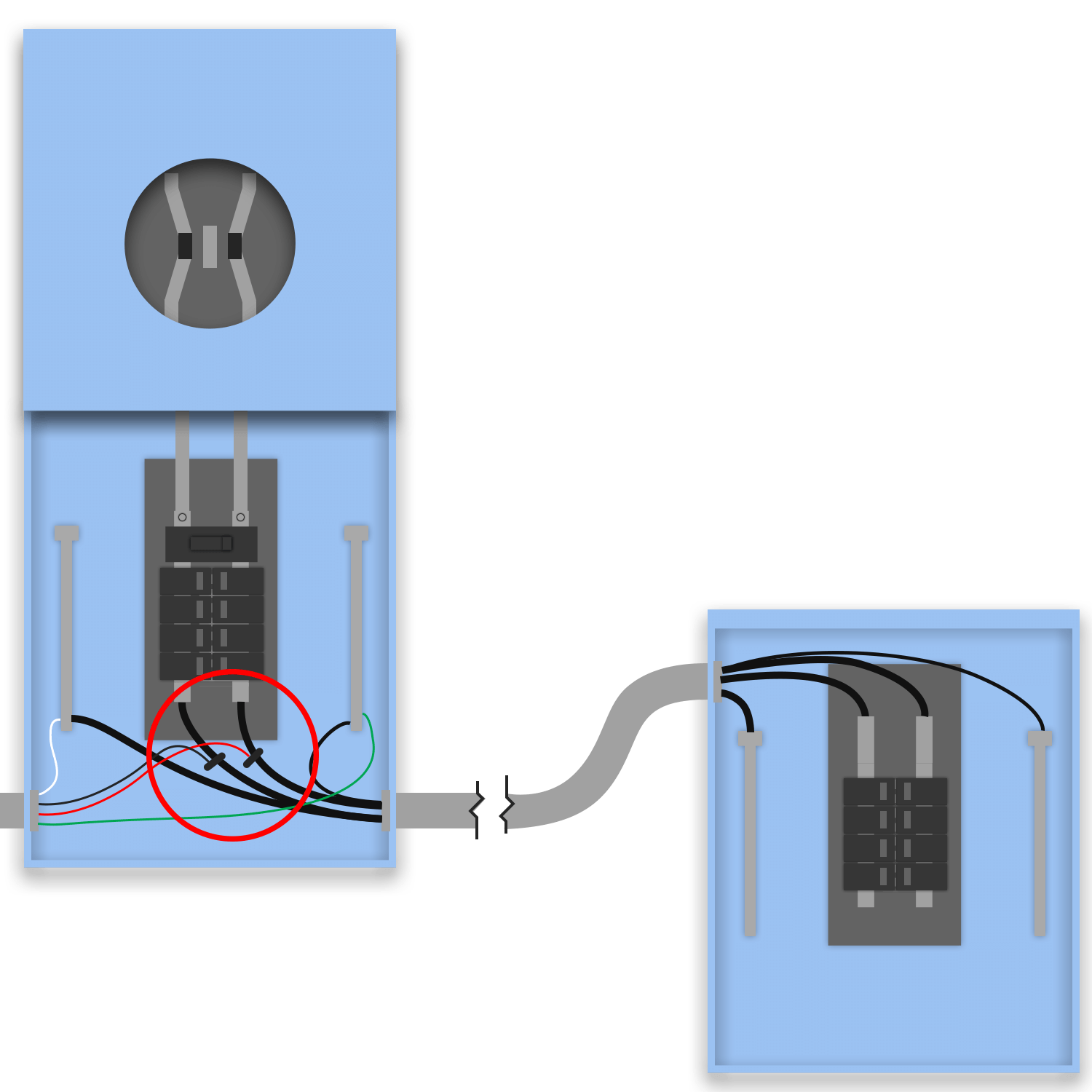
On a meter-main COMBO (one enclosure: meter + service main breaker + distribution bus), solar interconnects as a LOAD-SIDE TAP on the combo's feedthrough lugs through a fused AC disconnect. No separate downstream feedthrough panel is modeled, the tapped feedthrough conductors carry on to the dwelling loads. The tap is on the load side of the service main (NEC 705.12 load-side connection). A tap does not increase the feeder's load (PV is a source offsetting utility draw); post-tap the feeder is evaluated under NEC 705.12(A), Feeders and Feeder Taps. It complies via (A)(2)(b): an OCPD ≤ the feeder ampacity at the load-side connection. The 310.12(B) 83% main-feeder allowance was the pre-solar basis for the feeder size. The fused disconnect provides the OCPD the feedthrough conductors lack at the tap point.
Load-side feed-through tap on a meter-main combo's feedthrough lugs, no separate downstream panel. A tap does not increase the feeder's load (PV is a source offsetting utility draw); post-tap the feeder is evaluated under NEC 705.12(A), satisfied via (A)(2)(b), an OCPD ≤ the feeder ampacity at the load-side connection. The 310.12(B) 83% allowance was the pre-solar basis.
- 705.12(A): load-side feed-through connection (Article 705 reorganized in 2023)
- 705.13: Power Control Systems (alternative method; not used by a load-side tap)
- 240.21(B), 310.12(B), 250.122, 230: unchanged in concept
- 705.12(B)(2): load-side feed-through connection (the tapped feedthrough conductors)
- 240.21(B): feeder tap-conductor rules at the tap point
- 310.12(B): 83% single-phase dwelling main-feeder allowance; the pre-solar feeder basis. Post-tap the feeder is evaluated under 705.12(A)
- 250.122: EGC sizing from the circuit OCPD
- 230: meter-main combo service-disconnect requirements
- WITH A TAP the feeder is evaluated under 705.12(A): satisfy (A)(2)(b) [an OCPD ≤ the feeder ampacity at the load-side connection, e.g. a downstream panel main ≤ feeder ampacity] or (A)(2)(a) [feeder ampacity ≥ primary main OCPD + 125% PV]. (The 310.12(B) 83% allowance was the pre-solar basis.)
- No downstream feedthrough panel is modeled; the tapped conductors feed existing dwelling loads. If a downstream panel exists, protect it like Load Side Tap - Feedthrough with Main.
- A fused AC disconnect is required, the feedthrough conductors have no OCPD at the tap point (240.21(B)); utilities/AHJs also commonly require a visible lockable disconnect.
- The tap lands on feedthrough lugs (load side of the main), NOT a backfed breaker, the 120% busbar rule does not apply.
Load Side Tap - Feedthrough with MainNEC 705.12(B)(3)(6)
On a meter-main combo, solar taps the feedthrough conductors that feed an EXISTING downstream distribution panel, and that panel already has its OWN main breaker. The tap is on the load side of the combo main (NEC 705.12 load-side / feed-through), through a fused AC disconnect. A tap does not increase the feeder's load (PV is a source offsetting utility draw); post-tap the feeder is evaluated under NEC 705.12(A). Because the downstream panel's existing main is an OCPD ≤ the feeder ampacity at the load-side connection, the feeder is compliant via 705.12(A)(2)(b) without adding equipment, this is the clean case. Distinct from Load Side Tap - Feedthrough (No Main) (no downstream panel) and Load Side Tap - Meter-Main Disconnect (downstream panel is MLO and a main must be ADDED).
Load-side feed-through tap on a meter-main combo, feeding an existing downstream panel that already has its own main. A tap does not increase the feeder's load; post-tap the feeder is evaluated under 705.12(A) and is compliant via (A)(2)(b), the existing downstream main is an OCPD ≤ the feeder ampacity at the load-side connection. No added OCPD; the existing main's presence is why nothing new is required.
- 705.12(A): load-side feed-through connection (Article 705 reorganized in 2023)
- 240.21(B), 408.36, 310.12(B), 250.122: unchanged in concept
- 705.12(B)(2): load-side feed-through connection
- 240.21(B): feeder tap-conductor rules (satisfied at the load end by the existing downstream main)
- 408.36: the downstream panelboard's main provides its overcurrent protection (705.12(A)(2)(b))
- 310.12(B): 83% main-feeder allowance was the pre-solar feeder basis; post-tap the feeder is evaluated under 705.12(A)
- 250.122: EGC sizing
- This is the case where the downstream panel ALREADY has its own main, no breaker is added (contrast Load Side Tap - Meter-Main Disconnect, which converts an MLO panel and adds an (N) main).
- WITH A TAP the feeder is evaluated under 705.12(A): here it is satisfied via (A)(2)(b), verify the existing downstream panel main ≤ the feedthrough conductor ampacity. (The 310.12(B) 83% allowance was the pre-solar basis.)
- Fused AC disconnect required at the tap (240.21(B)); the tap is on feedthrough lugs, not a backfed breaker, so the 120% busbar rule does not apply.
Load Side Tap - New Feedthrough PanelNEC 705.12(B)(3)(6)
Same load-side feed-through tap on a meter-main combo, but here a NEW feedthrough panel (with its own main breaker) is INSTALLED downstream as part of the solar scope, rather than relying on an existing downstream panel. Solar taps the feedthrough conductors through a fused AC disconnect on the load side of the combo main. A tap does not increase the feeder's load (PV is a source offsetting utility draw); post-tap the feeder is evaluated under 705.12(A) and is compliant via (A)(2)(b), the new panel's main is an OCPD ≤ the feeder ampacity at the load-side connection. Use this when there is no suitable existing downstream panel, or the design intentionally adds a dedicated feedthrough/distribution panel. The new panel + its main are NEW equipment.
Load-side feed-through tap on a meter-main combo with a NEW downstream feedthrough panel (own main) installed. A tap does not increase the feeder's load; post-tap the feeder is evaluated under 705.12(A) and is compliant via (A)(2)(b), the new panel main is an OCPD ≤ the feeder ampacity at the load-side connection.
- 705.12(A): load-side feed-through connection (Article 705 reorganized in 2023)
- 240.21(B), 408.36, 310.12(B), 250.122, 250.24(A)(5): unchanged in concept
- 705.12(B)(2): load-side feed-through connection
- 240.21(B): feeder tap-conductor rules (satisfied at the load end by the new panel's main)
- 408.36: the new panelboard's main provides its overcurrent protection (705.12(A)(2)(b))
- 310.12(B): 83% main-feeder allowance was the pre-solar feeder basis; post-tap the feeder is evaluated under 705.12(A)
- 250.122: EGC sizing; 250.24(A)(5): N-G bond stays at the service main, the new downstream panel is NOT re-bonded
- The feedthrough panel + its main are NEW equipment (newEquipment:true), shown as new on the plan set.
- The new downstream panel is a sub-distribution panel: NO neutral-ground bond (250.24(A)(5) keeps the bond at the service main); 4-wire feeder with separate EGC.
- WITH A TAP the feeder is evaluated under 705.12(A): here it is satisfied via (A)(2)(b), the new downstream panel main ≤ the feedthrough conductor ampacity. (The 310.12(B) 83% allowance was the pre-solar basis.)
- SEGMENT SIZING (docs/FEEDTHROUGH_TAP_SIZING.md + docs/FEEDTHROUGH_TAP_CONDUCTOR_SIZING.md): the tap-to-new-main conductors are NEW wire sized to the new main (150A → 1/0 Cu), the main then meets 705.12(A)(2)(b) [2020: (B)(1)(b)] against that conductor exactly. NEC 310.12(B) is CONDUCTOR sizing for the dwelling feeder and never stops applying; 705.12 layers a separate test on top.
- CONTESTED, designer/AHJ decision: with a 150A inserted main, the EXISTING 83%-sized downstream conductor (#1 Cu, 130A) is protected at 150. One reading: (A)(2)(b) caps the device at the load-side portion ampacity and the downstream run is still load-side → violation. Counter-reading: the inserted OCPD terminates the tapped feeder and the downstream run is a distinct dwelling main-power feeder that 310.12(B) justifies at #1 under a 150A device, as on any non-solar dwelling. THE UNCONTESTED ALTERNATIVE: drop the inserted main to 125A (130A conductor at 125A is plain 240.4, no interpretation needed). When the AHJ is unknown, use 125A.
- Whether 240.4(B) next-size-up applies to the (A)(2)(b) device is an interpretation, not settled text, design as if it does not.
- Field notes: run a load check against the inserted main (at 125A it protects the entire dwelling); 2/0 AL is as common as #1 Cu in this role; 110.14(C) terminations can pull usable ampacity below the table; an enclosed breaker satisfies (b) without a panelboard; never backfeed PV into the inserted panel (705.12(B) busbar allowance ~25A).
Load Side Tap with DerateNEC 705.12(B)(3)(6)
Load-side feed-through tap on a meter-main combo (no separate downstream panel, like Load Side Tap - Feedthrough (No Main)), but the upstream combo MAIN breaker is DERATED to a smaller rating. A tap does not increase the feeder's load; post-tap the feeder is evaluated under 705.12(A). Derating the primary main lowers the (A)(2)(a) threshold (primary OCPD + 125% PV) the feeder must meet, so the existing (smaller) feedthrough conductors can satisfy (A)(2)(a). Use this when the existing feedthrough conductors are sized smaller than the original main and upsizing them isn't practical, derating the main lowers the threshold the conductors must meet instead. Solar still taps through a fused AC disconnect on the load side.
Load-side feed-through tap on a meter-main combo with the upstream main DERATED. A tap does not increase the feeder's load; post-tap the feeder is evaluated under 705.12(A). Derating the primary main lowers the (A)(2)(a) threshold (primary OCPD + 125% PV), so the (smaller) existing feedthrough conductors satisfy (A)(2)(a). Derate is the lever instead of upsizing conductors.
- 705.12(A): load-side feed-through connection (Article 705 reorganized in 2023)
- 240.21(B), 240.4, 310.12(B), 250.122: unchanged in concept
- 705.12(B)(2): load-side feed-through connection
- 240.21(B): feeder tap-conductor rules at the tap
- 240.4: the derated main as the primary-source OCPD in the 705.12(A)(2)(a) threshold (primary OCPD + 125% PV)
- 310.12(B): 83% allowance was the pre-solar feeder basis; post-tap the feeder is evaluated under 705.12(A)
- 250.122: EGC sizing
- The combo main is PHYSICALLY replaced with a smaller breaker (a real hardware change) sized so the derated primary main lowers the 705.12(A)(2)(a) threshold (primary OCPD + 125% PV) the existing feedthrough conductors must meet.
- No downstream feedthrough panel is modeled; the tapped conductors feed existing loads.
- WITH A TAP the feeder is evaluated under 705.12(A), derating the primary main lowers the (A)(2)(a) threshold (primary OCPD + 125% PV) the feeder must meet. (The 310.12(B) 83% allowance was the pre-solar basis.)
- Fused AC disconnect required at the tap (240.21(B)); tap on lugs, not a backfed breaker, 120% rule N/A.
Load Side Tap - Feedthrough with Main and DerateNEC 705.12(B)(3)(6)
Load-side feed-through tap on a meter-main combo feeding an EXISTING downstream panel that has its own main (like Load Side Tap - Feedthrough with Main), AND the upstream combo main is DERATED. A tap does not increase the feeder's load; post-tap the feeder is evaluated under 705.12(A). The existing downstream main already satisfies (A)(2)(b); derating the combo main additionally lowers the (A)(2)(a) threshold (primary OCPD + 125% PV) where the design wants margin on both paths. Combines two levers: the existing downstream main is an OCPD ≤ the feeder ampacity at the load-side connection (A)(2)(b), and the derated combo main lowers the (A)(2)(a) threshold, together keeping the feedthrough conductors compliant under 705.12(A).
Load-side feed-through tap on a meter-main combo, existing downstream panel with its own main, AND the upstream main derated. A tap does not increase the feeder's load; post-tap the feeder is evaluated under 705.12(A): the existing downstream main satisfies (A)(2)(b), and the derated combo main lowers the (A)(2)(a) threshold (primary OCPD + 125% PV). 705.12(A) + 240.4.
- 705.12(A): load-side feed-through connection (Article 705 reorganized in 2023)
- 240.21(B), 240.4, 408.36, 310.12(B), 250.122: unchanged in concept
- 705.12(B)(2): load-side feed-through connection
- 240.21(B): feeder tap-conductor rules
- 240.4: derated combo main as the primary-source OCPD in the 705.12(A)(2)(a) threshold
- 408.36: existing downstream panel main provides its protection (705.12(A)(2)(b))
- 310.12(B): 83% was the pre-solar feeder basis; post-tap the feeder is evaluated under 705.12(A) · 250.122: EGC
- Two levers at once: the existing downstream panel main satisfies 705.12(A)(2)(b), AND derating the combo main (hardware change) lowers the (A)(2)(a) threshold (primary OCPD + 125% PV).
- WITH A TAP the feeder is evaluated under 705.12(A); derating the primary main lowers the (A)(2)(a) threshold (primary OCPD + 125% PV) the feeder must meet. (The 310.12(B) 83% allowance was the pre-solar basis.)
- Fused AC disconnect required at the tap (240.21(B)); tap on lugs, not a backfed breaker, 120% rule N/A.
Load Side Tap - Meter-Main DisconnectNEC 705.12(B)(3)(6)
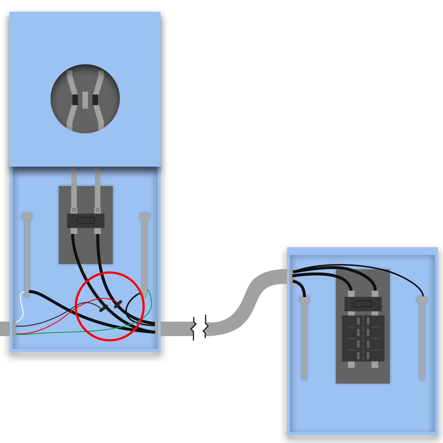
A combined meter-main disconnect is the service disconnect, it holds the meter, the service main breaker, the neutral-to-ground bond, and the grounding-electrode connection. It has no load distribution of its own; its feedthrough lugs carry the dwelling's power through feedthrough conductors to the downstream main distribution panel. Solar interconnects here as a LOAD-SIDE TAP on those feedthrough conductors (NEC 705.12(B)(3)(6)), through a fused AC disconnect. The tap lands on the meter-main disconnect's feedthrough lugs, upstream of the downstream panel's main breaker. The key NEC consequence is protection coordination, not overload. A tap does not increase the feeder's load, the feedthrough still serves the same subset of dwelling loads, and PV is a source that offsets utility draw. Before solar, the feedthrough conductors are the dwelling's main power feeder and may be sized at 83% of the service rating under NEC 310.12(B). The moment solar taps in, the feeder is evaluated under NEC 705.12(A), Feeders and Feeder Taps. Because the tap is not at the opposite end of the feeder from the primary OCPD, 705.12(A)(2) applies: the load-side portion must be protected by an OCPD ≤ the feeder ampacity at the load-side connection (A)(2)(b), or the feeder ampacity must be ≥ the primary-source OCPD + 125% PV (A)(2)(a). That is why the downstream feedthrough panel must be CONVERTIBLE and carry a MAIN BREAKER ≤ the feedthrough conductor ampacity, that main is the (A)(2)(b) OCPD at the load-side connection. An MLO downstream panel has no such OCPD, leaving the feeder without a 705.12(A)(2)(b) path, so a main breaker is added as part of the solar scope.
Load-side (feed-through) PV interconnection on a meter-main disconnect. The PV taps the feedthrough conductors between the service main and the downstream panel. A tap does not increase the feeder's load (PV is a source offsetting utility draw); post-tap the feeder is evaluated under NEC 705.12(A) and is made compliant via (A)(2)(b), an OCPD ≤ the feeder ampacity at the load-side connection, which requires the downstream panel to carry a main breaker ≤ the feeder ampacity.
- 705.12(A): load-side feed-through connection (Article 705 was reorganized in 2023; this is the authoritative renumbered citation from the NEC_REFS table, not a guess).
- 705.13: Power Control Systems: the 2023-emphasized alternative to the 120% busbar allowance (not used by a load-side TAP, but relevant when comparing connection methods).
- 240.21(B), 310.12(B), 250.122, 230: unchanged in concept between 2020 and 2023.
- 705.12(B)(2): load-side feed-through connection (the PV connects on the load side of the service main, tapping the feedthrough conductors).
- 240.21(B): Feeder tap-conductor rules governing the tap onto the feedthrough conductors.
- 310.12(B): 83% single-phase dwelling service/feeder allowance. The pre-solar basis for the feedthrough feeder size; post-tap the feeder is evaluated under 705.12(A).
- 250.122: EGC sizing from the circuit OCPD. (Project convention floors rooftop string EGCs at #6: see wire-sizing notes.)
- 230: Service disconnecting means / meter-main combination requirements.
- WITH A TAP the feeder is evaluated under 705.12(A), a tap does not increase the feeder's load, so this is a protection-coordination rule, not an overload rule. Satisfy (A)(2)(b) [a downstream main ≤ the feeder ampacity at the load-side connection] or (A)(2)(a) [feeder ampacity ≥ primary main OCPD + 125% PV]. (The 310.12(B) 83% allowance was the pre-solar basis.) A feeder sized at 83% (e.g. 2/0 Cu on a 200A main) typically takes the (A)(2)(b) path via a downstream main sized to its actual ampacity.
- The tap lands on the meter-main disconnect feedthrough lugs (load side of the service main), NOT a backfed breaker. The 120% busbar rule (705.12 backfeed-breaker provision) therefore does NOT govern the tap; the governing limits are tap-conductor ampacity (240.21(B)) and the downstream panel main.
- A FUSED AC disconnect is required at the tap: the tapped feedthrough conductors have no OCPD at the tap point, so the disconnect provides it (240.21(B)); utilities/AHJs also commonly require a visible lockable disconnect.
- NEC 2020 and 2023 cite different 705.12 subsections (Article 705 was reorganized): 705.12(B)(3)(6) → 705.12(B)(5). The codeBasis citations above are resolved per-edition from the canonical NEC_REFS table, but always confirm against the jurisdiction's adopted edition before stamping.
Load Side Tap - New Feedthrough (Meter-Main Disconnect)NEC 705.12(B)(3)(6)
On a meter-main DISCONNECT service (combined meter + service main breaker + N-G bond + GES, no load distribution of its own), solar taps the disconnect's feedthrough lugs and a NEW feedthrough panel (with its own main) is installed downstream to host the dwelling loads. The tap is on the load side of the disconnect main, through a fused AC disconnect. This is the NEW-panel counterpart to Load Side Tap - Meter-Main Disconnect (which converts an existing MLO downstream panel). A tap does not increase the feeder's load; post-tap the feeder is evaluated under 705.12(A) and is compliant via (A)(2)(b), the new panel's main is an OCPD ≤ the feeder ampacity at the load-side connection. The new panel + its main are NEW equipment.
Load-side feed-through tap on a meter-main disconnect, with a NEW downstream feedthrough panel (own main) installed. A tap does not increase the feeder's load; post-tap the feeder is evaluated under 705.12(A) and is compliant via (A)(2)(b), the new panel main is an OCPD ≤ the feeder ampacity at the load-side connection. (The 310.12(B) 83% allowance was the pre-solar basis.)
- 705.12(A): load-side feed-through connection (Article 705 reorganized in 2023)
- 240.21(B), 408.36, 310.12(B), 250.122, 250.24(A)(5): unchanged in concept
- 705.12(B)(2): load-side feed-through connection
- 240.21(B): feeder tap-conductor rules (load-side connection satisfied by the new panel main, 705.12(A)(2)(b))
- 408.36: new panelboard main provides its overcurrent protection
- 310.12(B): 83% main-feeder allowance was the pre-solar feeder basis; post-tap the feeder is evaluated under 705.12(A)
- 250.122: EGC; 250.24(A)(5): N-G bond stays at the meter-main disconnect, new downstream panel NOT re-bonded
- NEW feedthrough panel + its main are NEW equipment. The meter-main disconnect remains the service disconnect (bond + GES); the new panel is a sub-distribution panel, no re-bond, 4-wire feeder with separate EGC.
- WITH A TAP the feeder is evaluated under 705.12(A): here it is satisfied via (A)(2)(b), the new downstream panel main ≤ the feedthrough conductor ampacity. (The 310.12(B) 83% allowance was the pre-solar basis.)
- Fused AC disconnect required at the tap (240.21(B)); tap lands on the disconnect feedthrough lugs, not a backfed breaker, 120% rule N/A.
Load Side Tap with Derate - Meter-Main DisconnectNEC 705.12(B)(3)(6)
The derate variant of Load Side Tap - Meter-Main Disconnect. On a meter-main DISCONNECT service, solar taps the disconnect's feedthrough lugs feeding the dwelling's existing downstream panel, which was MLO, so a main breaker is ADDED (convertible panel, shown (N)), AND the meter-main disconnect's main is DERATED. A tap does not increase the feeder's load; post-tap the feeder is evaluated under 705.12(A). The added downstream main is an OCPD ≤ the feeder ampacity at the load-side connection (A)(2)(b), and derating the disconnect main additionally lowers the (A)(2)(a) threshold (primary OCPD + 125% PV) where the design wants margin on both paths. Use when the design wants both levers, the added downstream main plus a lowered (A)(2)(a) threshold on the (smaller) existing feedthrough conductors.
Load-side feed-through tap on a meter-main disconnect: a main breaker is ADDED to the (formerly MLO) downstream panel (convertible, shown (N)) AND the upstream disconnect main is DERATED. A tap does not increase the feeder's load; post-tap the feeder is evaluated under 705.12(A): the added downstream main satisfies (A)(2)(b), and the derated disconnect main lowers the (A)(2)(a) threshold (primary OCPD + 125% PV). 705.12(A) + 240.4.
- 705.12(A): load-side feed-through connection (Article 705 reorganized in 2023)
- 240.21(B), 240.4, 408.36, 310.12(B), 250.122: unchanged in concept
- 705.12(B)(2): load-side feed-through connection
- 240.21(B): feeder tap-conductor rules
- 240.4: derated disconnect main as the primary-source OCPD in the 705.12(A)(2)(a) threshold; added downstream main as the (A)(2)(b) OCPD
- 408.36: added main converts the MLO downstream panel to a protected panelboard (705.12(A)(2)(b))
- 310.12(B): 83% was the pre-solar feeder basis; post-tap the feeder is evaluated under 705.12(A) (hence both derate AND added main) · 250.122: EGC
- Two changes at once: a main breaker is ADDED to the downstream MLO panel (NEW, shown (N)) AND the meter-main disconnect main is DERATED (hardware change).
- WITH A TAP the feeder is evaluated under 705.12(A): the added main satisfies (A)(2)(b) and derating the disconnect main lowers the (A)(2)(a) threshold (primary OCPD + 125% PV). (The 310.12(B) 83% allowance was the pre-solar basis.)
- Fused AC disconnect required at the tap (240.21(B)); tap lands on the disconnect feedthrough lugs, not a backfed breaker, 120% rule N/A.
- The feedthrough-tap-conductor-protection design check fires until the downstream main is present (see designCheckEngine feedthrough_tap_unprotected_conductors).
Supply-Side / Line-Side Connection
Connection ahead of the service disconnect (NEC 705.11), with no busbar 120% limit, but its own conductor and disconnect rules.
Supply Side ConnectionNEC 705.11
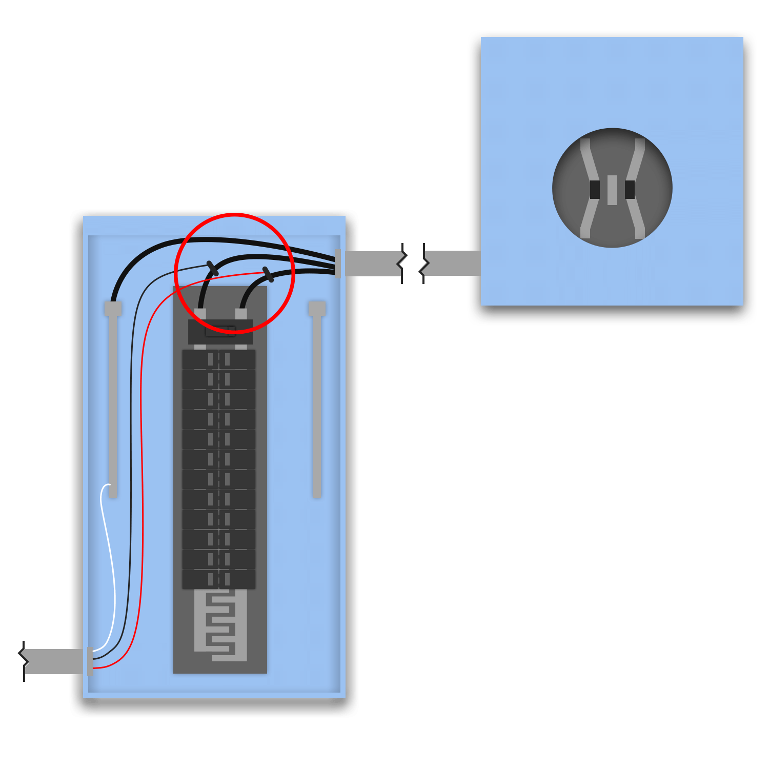
On a Separate MDP service (meter → main panel), solar connects on the SUPPLY (line) side: it taps the service-entrance conductors between the meter and the main panel, AHEAD of the service main breaker, through a FUSED AC disconnect. Because the connection is on the line side of the service disconnect, the panel-busbar rules of 705.12 (120% / sum) do NOT apply, this is governed by NEC 705.11. The fused disconnect supplies the overcurrent protection the tapped service conductors otherwise lack, and becomes a (PV) service disconnect: neutral-ground bonded with a grounding-electrode connection. The limiting math is the SERVICE ampacity (sum of supply-side sources), not a busbar.
Supply-side (line-side) PV connection on the service-entrance conductors ahead of the service main. Governed by 705.11, NOT the 705.12 busbar rules. A fused disconnect provides OCPD, the sum of supply-side source ratings must stay within the service ampacity, and the unprotected tap conductors are length-limited inside the building.
- 705.11: supply-side source connection (705.11 is stable across editions)
- 705.11(B)(2): unprotected tap-conductor length limit (renumbered from 705.11(C))
- 705.28, 250.24(A)(5), 312.8(A): unchanged in concept
- 705.11: supply-side (line-side) source connection
- 705.11(B)(1): sum of supply-side source OCPD ratings ≤ service conductor / equipment ampacity
- 705.28: tap-conductor sizing (min 6 AWG Cu)
- 705.11(C): max length of unprotected tap conductors inside the building
- 250.24(A)(5): N-G bond + grounding-electrode connection at the PV service disconnect
- 312.8(A): wiring-space fill where the tap shares an enclosure
- Connect AHEAD of the service main → the 705.12 panel-busbar 120% / sum rules DO NOT apply. The governing limit is service ampacity (705.11(B)(1)), not busbar rating.
- The PV disconnect MUST be FUSED, supply-side conductors have no upstream OCPD, so the disconnect provides it (705.11). A non-fused switch leaves the tapped conductors unprotected.
- Tap conductors from the tap point to the PV disconnect are UNPROTECTED, length inside the building is limited per §705.11(C): 10 ft residential, 16.5 ft commercial (71 ft with cable limiters).
- The PV disconnect becomes a service disconnect: N-G bonded, grounding-electrode connection per 250.24.
Supply Side with Wire TroughNEC 705.11
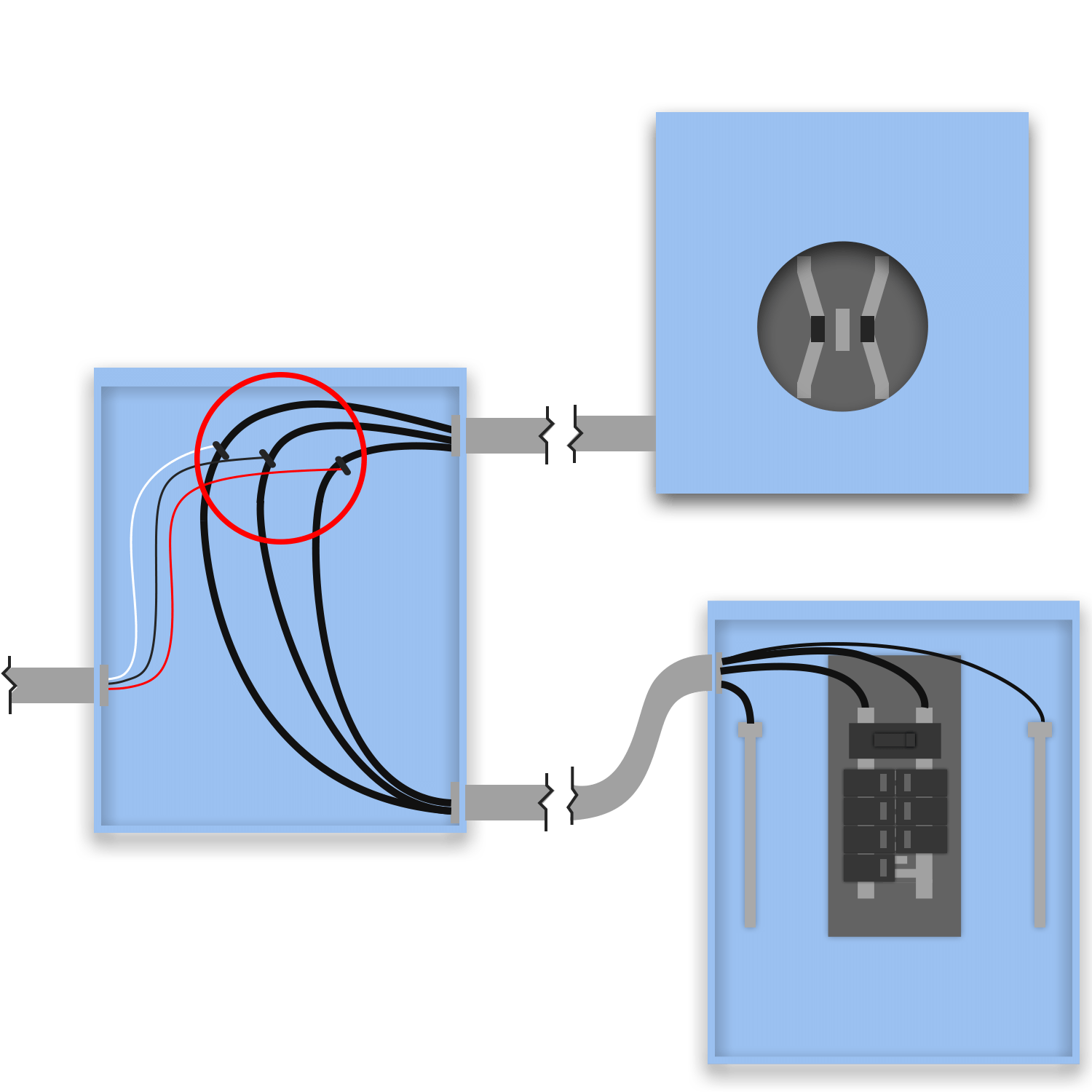
Same supply-side (line-side) connection as Supply Side Connection, but the tap is made inside a WIRE TROUGH (auxiliary gutter) installed between the meter and the main panel rather than as an in-panel tap. The trough gives clean, accessible space to land the line-side tap connectors and route the PV feeder to its fused disconnect, useful when the existing meter/panel has no room for the tap. NEC 705.11 governs; the trough must meet wiring-space fill (312.8).
Supply-side line-side connection made in a wire trough between meter and main panel. 705.11 supply-side rules apply; the trough is an auxiliary gutter subject to 312.8 fill. Fused disconnect provides OCPD; sum of sources ≤ service ampacity.
- 705.11: supply-side source connection (705.11 stable)
- 705.11(B)(2): tap length limit (renumbered from 705.11(C))
- 705.28, 366.22/376.22, 312.8(A), 250.24(A)(5): unchanged in concept
- 705.11: supply-side (line-side) source connection
- 705.11(B)(1): sum of supply-side source ratings ≤ service ampacity
- 705.28: tap-conductor sizing (min 6 AWG Cu)
- 705.11(C): unprotected tap-conductor length limit
- 366.22 / 376.22: auxiliary gutter / wireway fill + ampacity-adjustment; 312.8(A): enclosure fill
- 250.24(A)(5): N-G bond at the PV service disconnect
- The wire trough is an auxiliary gutter / wireway: respect its fill + the >30-conductor ampacity-adjustment rules (366.22 / 376.22) in addition to 312.8.
- Still a 705.11 supply-side connection, no 705.12 busbar rule; fused PV disconnect provides OCPD; unprotected tap length limited inside the building.
- Sum of supply-side source ratings ≤ service conductor / equipment ampacity (705.11(B)(1)).
Supply Side + Fused MainNEC 705.11
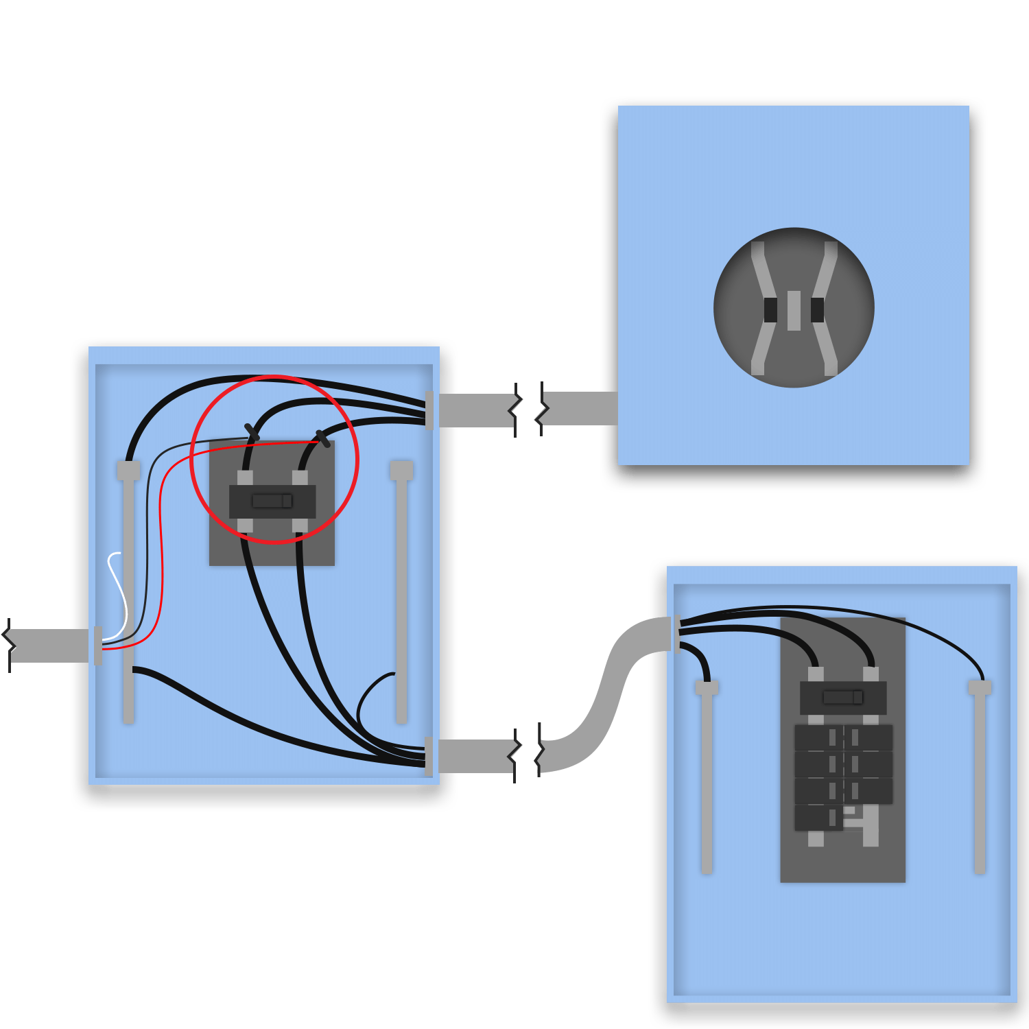
A NEW fused service main disconnect is installed between the meter and the existing main panel; solar taps the line (supply) side of that new disconnect. Installing a service disconnect ahead of the panel demotes the existing panel to a downstream feeder/sub panel and MOVES the service-entrance role (N-G bond + grounding electrode) to the new disconnect (NEC 250.24(A)(5)). This is the supply-side answer when the existing panel busbar can't accommodate a backfeed breaker (120% fails) and a clean line-side tap point is wanted: the new fused disconnect both creates the tap point and provides the service OCPD. The new disconnect + its fuses are NEW equipment.
Supply-side connection at a NEWLY installed fused service main disconnect ahead of the existing panel. New disconnect becomes the service disconnect (bond/GES move to it, 250.24); solar taps its line side. 705.11 supply-side rules; 705.12 busbar rule does not apply.
- 705.11: supply-side source connection (705.11 stable)
- 705.11(B)(2): tap length limit (renumbered from 705.11(C))
- 230.71, 250.24(A)(5), 705.28: unchanged in concept
- 705.11: supply-side (line-side) source connection at the new disconnect
- 705.11(B)(1): sum of supply-side source ratings ≤ service ampacity
- 230.71: the new disconnect is the single service disconnecting means
- 250.24(A)(5): N-G bond + grounding-electrode connection MOVE to the new disconnect (existing panel becomes a sub/feeder panel, un-bonded)
- 705.28: tap-conductor sizing · 705.11(C): unprotected tap length limit
- Installing the new SD DEMOTES the existing main panel: its main breaker becomes a sub-feed (or it goes MLO), and its N-G bond is REMOVED (250.24(A)(5), bond lives only at the new service disconnect).
- New disconnect + fuses are NEW equipment; rate it to match the existing service (230.79) unless a service upgrade is intended.
- Supply-side: 705.11 governs, not the 705.12 busbar 120% rule; the new fused disconnect provides the service OCPD.
Supply Side + Breaker MainNEC 705.11
Identical topology to Supply Side + Fused Main, but the new service main disconnect is BREAKER-protected (a main breaker) rather than fusible. The OCPD for the service comes from the new disconnect's main breaker instead of fuses. Installer/AHJ choice driven by stock and preference; both are NEC 705.11-compliant. The new disconnect becomes the service disconnect (bond + GES move to it), the existing panel is demoted, and solar taps the line side of the new disconnect through its own fused PV disconnect.
Supply-side connection at a NEWLY installed BREAKER-based (non-fusible) service main disconnect. Same as Supply Side + Fused Main but service OCPD is the new disconnect's main breaker, not fuses. 705.11 supply-side; bond/GES move to the new disconnect.
- 705.11: supply-side source connection (705.11 stable)
- 705.11(B)(2): tap length limit (renumbered from 705.11(C))
- 230.71, 230.79, 250.24(A)(5), 705.28: unchanged in concept
- 705.11: supply-side source connection at the new breaker disconnect
- 705.11(B)(1): sum of supply-side source ratings ≤ service ampacity
- 230.71: single service disconnecting means · 230.79: SD rating ≥ service load
- 250.24(A)(5): bond + GES move to the new disconnect; existing panel un-bonded
- 705.28 · 705.11(C): tap sizing + unprotected length
- OCPD difference vs Supply Side + Fused Main: the new disconnect carries a MAIN BREAKER (non-fusible), that breaker is the service OCPD.
- New SD rating defaults to the existing service capacity (230.79); the existing panel is demoted + un-bonded (250.24(A)(5)).
- Supply-side: 705.11 governs; no 705.12 busbar 120% rule.
Supply Side - New Main Disconnect (No Main)NEC 705.11
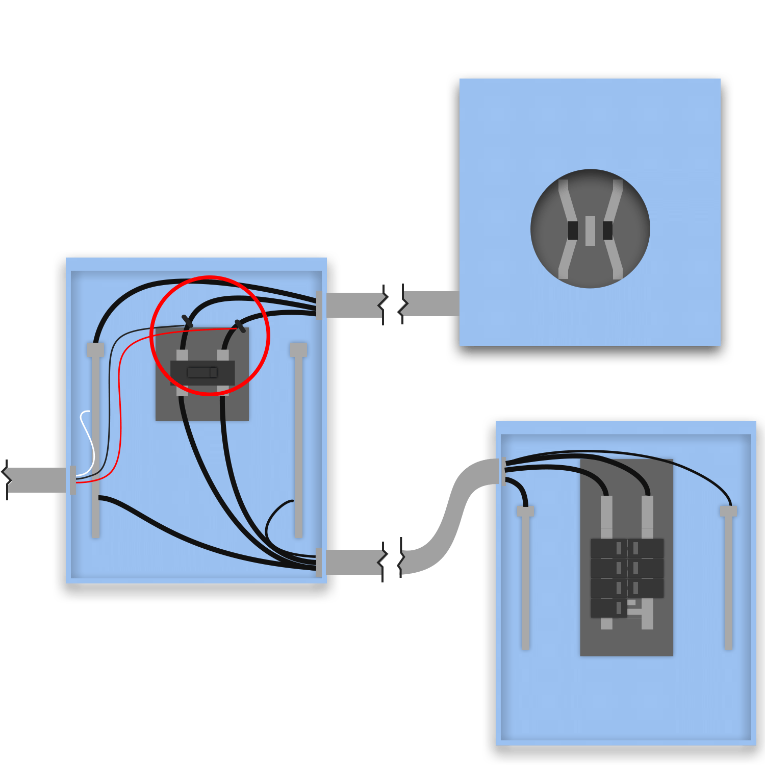
A new fused MLO (main-lug-only) service disconnect is installed ahead of the existing panel, and solar taps its line side. Used when the EXISTING main panel has no main breaker, historically a "six-handle" service where up to six disconnects served as the service disconnecting means (NEC 230.71). Rather than rely on that arrangement, a new fused MLO disconnect establishes a single, clearly fused service disconnect; the existing panel becomes a downstream feeder panel. Solar connects supply-side at the new disconnect through its own fused PV disconnect.
Supply-side connection at a NEW fused MLO service disconnect installed ahead of a main-less (legacy six-handle) existing panel. The new fused disconnect becomes the single service disconnect with OCPD via its fuses; 705.11 supply-side rules apply.
- 705.11: supply-side source connection (705.11 stable)
- 230.71: note the 2023 single-disconnect emphasis (the six-handle allowance was tightened in recent cycles)
- 705.11(B)(2), 705.28, 250.24(A)(5): unchanged in concept
- 705.11: supply-side source connection at the new disconnect
- 230.71: consolidates a legacy multi-handle service into a single service disconnecting means
- 705.11(B)(1): sum of supply-side source ratings ≤ service ampacity
- 250.24(A)(5): bond + GES at the new disconnect
- 705.28 · 705.11(C): tap sizing + unprotected length
- Specifically for an EXISTING MLO / legacy six-handle panel (no single main). The new fused MLO disconnect provides the single service disconnecting means + OCPD.
- NEC 2023 tightened the multiple-service-disconnect allowance toward a single disconnect, confirm the AHJ's adopted edition treatment of 230.71 for the existing arrangement.
- Supply-side: 705.11 governs; the new fused disconnect provides OCPD; unprotected tap length limited inside the building.
Supply Side with BreakerNEC 705.11
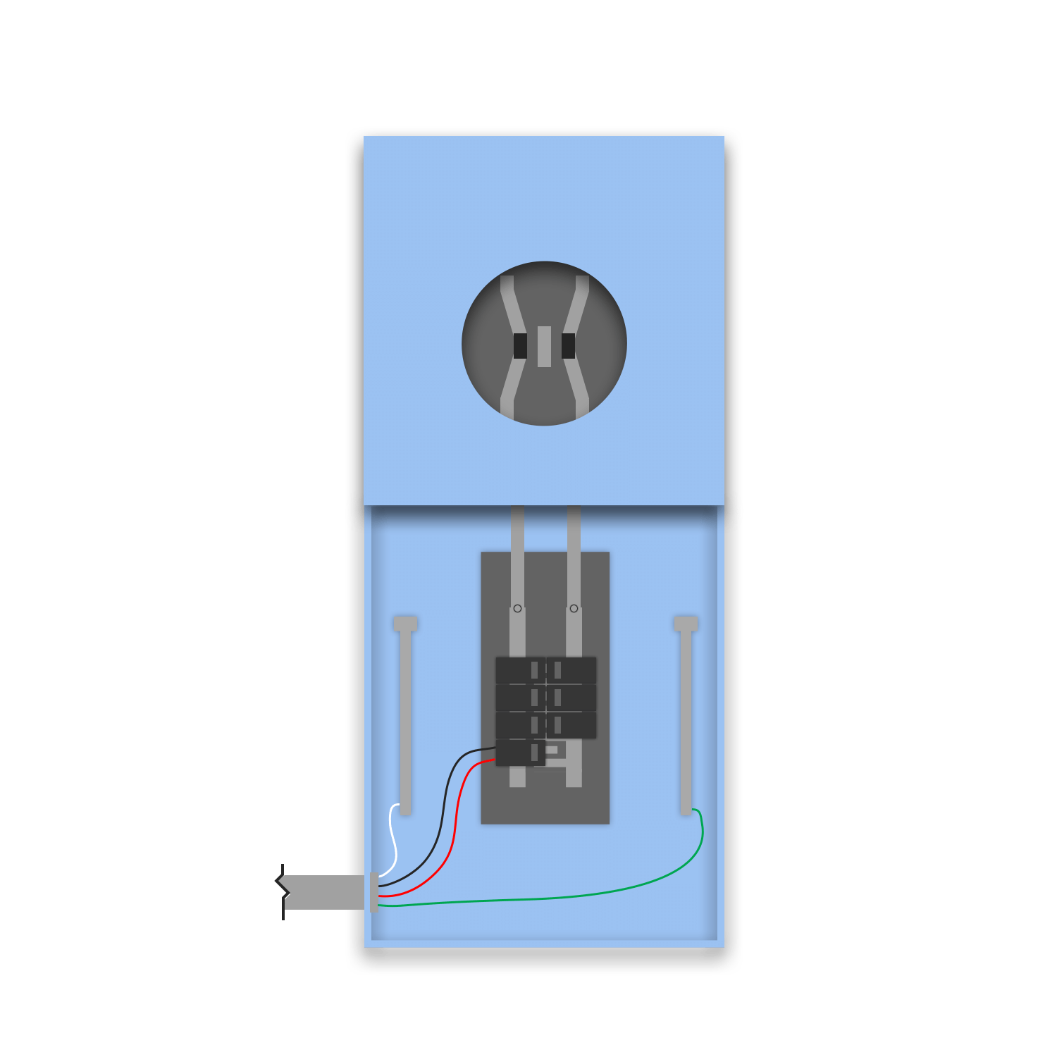
Solar lands on a BACKFED BREAKER in an MLO (main-lug-only) panel that has NO main breaker. Electrically this is a SUPPLY-SIDE connection, not a 120% install: with no main breaker on the bus there is nothing to bound a 120% calc, and each breaker in an MLO service panel is itself one of the service disconnecting means (NEC 230.71, the "six-handle" rule). So the PV breaker is treated as an added service disconnect under 705.11, and the limit is the service ampacity (sum of all the disconnects/sources), NOT a busbar 120% figure. This is the classifier's "MLO override": a backfed breaker on a main-less bus is reclassified from oneTwentyRule to supplySide.
Backfed PV breaker on an MLO service panel (no main). Treated as supply-side per 705.11, each breaker is a service disconnect (230.71), the 120% busbar rule does NOT apply (no main to bound it), and the governing limit is service ampacity. This is the "MLO override" in the classifier.
- 705.11: supply-side source connection (705.11 stable)
- 230.71 (230.71): NOTE: 2023 tightened the multi-disconnect allowance toward a SINGLE service disconnect; an MLO six-handle service may no longer comply for new work: confirm the adopted edition
- 705.11(B)(1), 408.36, 250.24(A)(5): unchanged in concept
- 705.11: supply-side source connection (MLO bus, no main → line-side treatment)
- 230.71 (230.71): each breaker is one of the service disconnecting means (six-handle rule)
- 705.11(B)(1): sum of source ratings ≤ service conductor / equipment ampacity
- 408.36: MLO panelboard protected by upstream service OCPD, not an internal main
- 250.24(A)(5): service N-G bond + GES on the MLO service panel
- The 705.12 120% busbar rule does NOT apply, there is no main breaker on the MLO bus to bound it. Sizing is by service ampacity (705.11), not busbar × 1.20.
- ⚠️ NEC 2023 moved toward a SINGLE service disconnect (230.71), the legacy six-handle MLO arrangement this entry relies on may not be permitted for NEW services under 2023. Verify the AHJ edition before specifying.
- Because it is a supply-side connection, OCPD/disconnect rules of 705.11 apply even though the device looks like an in-panel backfeed breaker.
Supply Side - Main DisconnectNEC 705.11
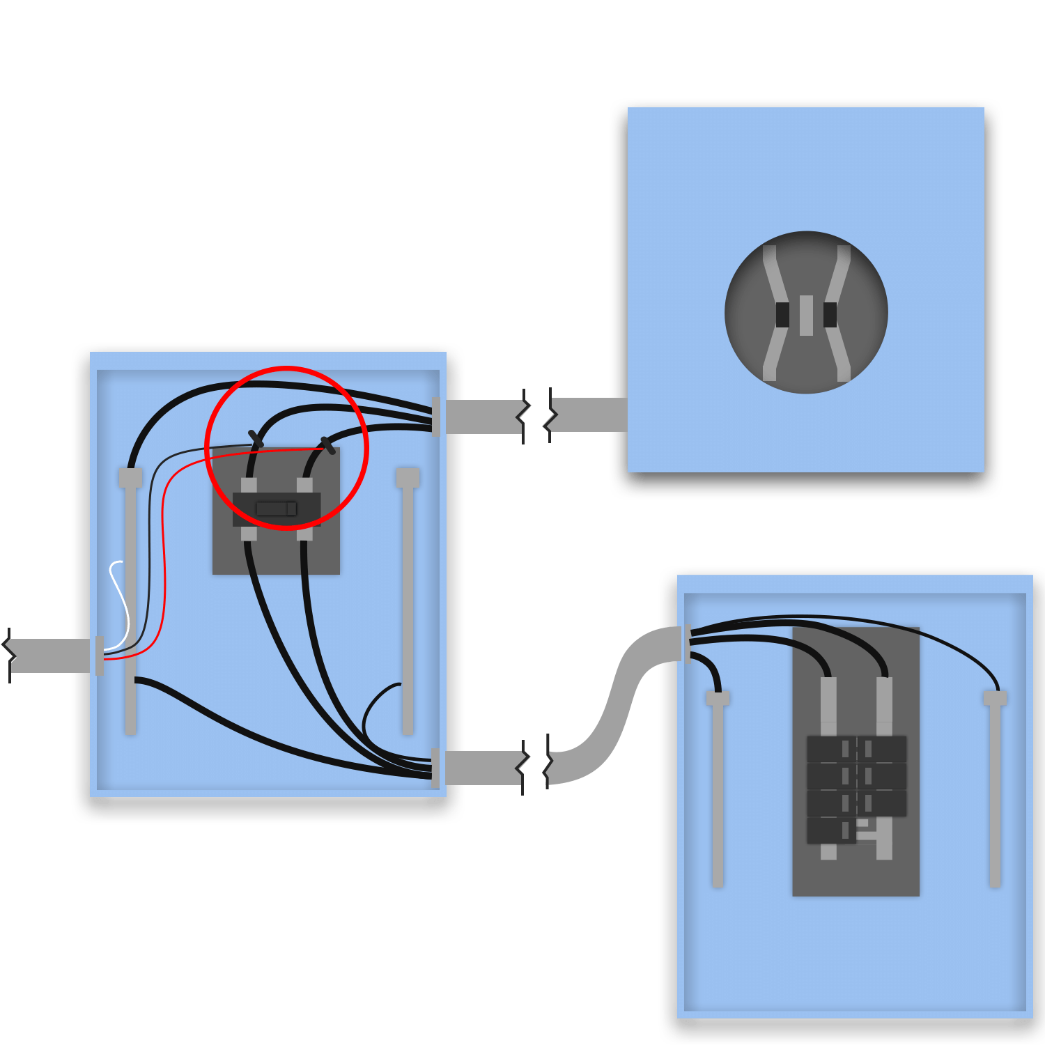
On a Separate Disconnect service (meter → main disconnect → downstream panel), solar taps the line (supply) side conductors AT the existing main disconnect, through a fused PV disconnect. The connection is ahead of the existing service main, so it is a 705.11 supply-side connection, no 705.12 busbar rule. The existing main disconnect remains the service disconnect (keeps its bond/GES); the PV fused disconnect provides OCPD for the tapped conductors. Distinct from Supply Side Connection (Separate MDP) only by where the line-side conductors live, at a standalone disconnect rather than between meter and main panel.
Supply-side tap at the existing main disconnect on a Separate Disconnect service. 705.11 line-side rules; existing disconnect stays the service disconnect; fused PV disconnect provides OCPD; sum of sources ≤ service ampacity.
- 705.11: supply-side source connection (705.11 stable)
- 705.11(B)(2): tap length limit (renumbered from 705.11(C))
- 705.28, 250.24(A)(5): unchanged in concept
- 705.11: supply-side source connection at the existing main disconnect
- 705.11(B)(1): sum of supply-side source ratings ≤ service ampacity
- 705.28: tap-conductor sizing (min 6 AWG Cu)
- 705.11(C): unprotected tap-conductor length limit
- 250.24(A)(5): N-G bond / GES remain at the existing service disconnect
- The EXISTING main disconnect stays the service disconnect (bond + GES unchanged), unlike the Supply Side + Fused Main family, no new service equipment is added.
- Supply-side: 705.11 governs, not 705.12; the PV disconnect must be FUSED to protect the tapped line-side conductors.
- Unprotected tap-conductor length inside the building is limited per §705.11(C): 10 ft residential, 16.5 ft commercial (71 ft with cable limiters).
Supply Side - Main Disconnect (Lug/Polaris)NEC 705.11
Same supply-side connection at the existing main disconnect as Supply Side - Main Disconnect, but the line-side tap is made with a LUG or POLARIS (insulated multi-tap) connector on the service conductors rather than an in-enclosure tap kit. The Polaris/lug connector must be listed and rated for supply-side use (the conductors are unfused at that point). NEC 705.11 governs; the connector method is a means of making the tap, not a different interconnection, the fused PV disconnect still provides OCPD and the existing main disconnect stays the service disconnect.
Supply-side tap at the existing main disconnect using a listed lug/Polaris connector. Same 705.11 basis as Supply Side - Main Disconnect; the difference is the connector method (must be listed + rated for supply-side / line-side use).
- 705.11: supply-side source connection (705.11 stable)
- 705.11(B)(2): tap length limit (renumbered from 705.11(C))
- 110.14(A), 705.11(B)(1), 705.28, 250.24(A)(5): unchanged in concept
- 705.11: supply-side source connection at the existing main disconnect
- 110.14(A) / listed Polaris (insulated multi-tap) connector rated for supply-side use
- 705.11(B)(1): sum of supply-side source ratings ≤ service ampacity
- 705.28: tap-conductor sizing · 705.11(C): unprotected length limit
- 250.24(A)(5): bond / GES remain at the existing service disconnect
- The ONLY difference from Supply Side - Main Disconnect is the tap method: a listed lug/Polaris connector instead of an in-panel tap. The connector must be listed + rated for supply-side (line-side) use (110.14).
- Still 705.11 supply-side: fused PV disconnect provides OCPD; existing main disconnect stays the service disconnect (bond/GES unchanged).
- Unprotected tap-conductor length inside the building is limited (supplyTapLength).
NEC references
- 705.12: Load-side (busbar) interconnection, 120% rule, sum rule, feed-through tap
- 705.11: Supply-side (line-side) connection ahead of the service disconnect
- 690.8(A)/(B): PV breaker sized to 125% of continuous inverter output current
- 408.36: Panelboard overcurrent protection. 250.122: equipment grounding conductor
- Edition-aware: citations shown for both NEC 2020 and NEC 2023 (Article 705 was reorganized in 2023)
The same calculations, running live as you design.
Solar Design Lab runs this calculator (and a dozen more) live as you build plansets. First planset free, then from $29 per planset.